

How does a digital signal become a measurable electromagnetic transmission? And what happens when noise, filtering, antennas and propagation change its behaviour? FreeScopes Basic III and IV connect these questions in a hands-on engineering laboratory.
A signal-processing engineer and an RF engineer may work on different parts of a system, but they are ultimately dealing with the same signal.
One considers sampling rates, Fourier transforms, modulation, filtering and signal-to-noise ratios. The other considers antennas, impedance, propagation losses, reflections and the transmission channel.
In a functioning radar or communication system, these two worlds cannot be separated.
Yet they are frequently taught separately.
Students may learn how to calculate a Fourier transform without understanding what the resulting spectrum means for a transmitter. They may study antenna gain without seeing how the received signal changes when antenna orientation, polarisation or propagation conditions vary.
The challenge is not a lack of mathematical knowledge. It is the difficulty of connecting mathematical models with observable system behaviour.
This is where interactive signal-processing and RF laboratories can make a difference.
Why is signal processing difficult to teach?
Consider a relatively simple question:
What happens when a signal is sampled at an insufficient sampling frequency?
Most engineering students will recognise the Nyquist-Shannon sampling theorem. They may correctly explain that sampling below the required rate can produce aliasing.
But can they recognise aliasing in a measured or simulated signal?
Can they distinguish it from noise or modulation effects?
Can they change the sampling frequency and explain the resulting spectral changes?
These are different levels of competence.
Knowing the theorem is the beginning. Being able to apply it, interpret the result and identify an error is the next step.
With FreeScopes Basic III, students can construct signal-processing chains, adjust their parameters and observe the resulting changes.
Instead of merely reading about sampling, they can investigate its effects.
What does FreeScopes Basic III teach?
FreeScopes Basic III focuses on the mathematical and digital behaviour of signals.
Its exercises address fundamental concepts used across radar, communications, navigation and other electronic systems.
The training topics include:
- Signal generation and waveform characteristics
- Continuous and discrete-time signals
- Sampling, aliasing and quantisation
- Pulse generation, pulse width and pulse repetition frequency
- Amplitude, frequency and digital modulation
- Fourier transforms and spectral analysis
- Filtering and signal reconstruction
- Noise, signal-to-noise ratio and channel capacity
- Signal energy and power
- Digital communication quality, eye diagrams and constellation diagrams
Consider three examples of how these concepts can be taught practically.
1. What happens when we change the sampling rate?
A student generates a signal, samples it and examines its frequency spectrum.
By reducing the sampling frequency, the student can observe how spectral components become incorrectly represented.
The exercise can then be extended:
- What happens if the signal contains several frequency components?
- What changes when the input bandwidth increases?
- Can filtering prevent the observed problem?
- How does the frequency-domain representation help identify aliasing?
The trainee moves from knowing a theorem to diagnosing a signal-processing error.
2. How can we visualise and evaluate digital communication signals?
Digital communication introduces another challenge.
A signal may be perfectly recognisable at the transmitter but become increasingly difficult to decode after noise or distortion is introduced.
FreeScopes Basic III includes digital-modulation exercises using constellation diagrams, eye diagrams and bit-error-rate analysis.
Consider a QPSK (Quadrature Phase Shift Keying) exercise. The trainee generates a random bit sequence, maps the bits to QPSK symbols, increases the number of samples per symbol through upsampling and applies pulse shaping.
The resulting signal can be examined through several complementary visualisations.
The constellation diagram shows the four possible QPSK symbol positions in the complex signal plane. The time-domain representation illustrates the changing signal values, while the eye diagram overlays successive symbol intervals to reveal characteristics of the signal's timing and waveform.
FreeScopes can display the eye diagram as individual traces or as a density-based heatmap, making it easier to recognise recurring signal patterns.
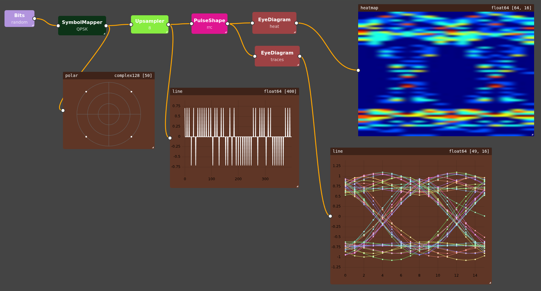
Figure 1 — FreeScopes Basic III: QPSK signal generation, symbol mapping, upsampling and pulse shaping, with constellation, time-domain and eye-diagram visualisations.
The trainee can then investigate how changes in pulse shaping, sampling and, in extended exercises, noise or timing disturbances affect these representations.
An open eye generally indicates a greater margin for distinguishing digital symbols. Noise, timing jitter and inter-symbol interference can reduce this margin.
The educational value lies in connecting the signal-processing blocks with their observable effects: the student sees not only the final diagram, but also how the signal was constructed.
This transforms digital-modulation theory into an experiment that can be modified, observed and analysed.
3. What does a filter actually do to a signal?
Filtering is often introduced mathematically through transfer functions and frequency responses.
In FreeScopes, trainees can work with signal generators, noise sources, filters and visualisation blocks to compare input and output signals.
They can investigate why a filter removes certain frequency components, what happens to the waveform and why filtering may also remove information that the receiver needs.
The objective is not simply to demonstrate that a filter works.
It is to understand which information the filter preserves, which information it suppresses and why that matters.
Where does digital signal processing end and RF engineering begin?
Imagine that a student has successfully generated and processed a signal.
The signal looks correct in the time domain. Its spectrum has the expected shape. Modulation and filtering behave as intended.
Now the signal must be transmitted.
Suddenly, additional questions arise.
- What antenna should be used?
- How does antenna gain influence the received power?
- What happens if transmitter and receiver have different polarisations?
- How much signal power is lost over distance?
- What happens when the transmission path contains reflections?
- How does an impedance mismatch affect power transfer?
These are the questions addressed by FreeScopes Basic IV – RF, Antennas & Propagation.
Basic III investigates the signal itself. Basic IV investigates what happens to that signal along the physical transmission path.
The two modules form a continuous engineering learning experience.
How do antenna characteristics influence a signal?
An antenna is not simply a component that radiates energy.
Its characteristics determine how energy is distributed in space and how effectively a signal can be received from a particular direction.
FreeScopes Basic IV includes antenna models and polar visualisations that allow trainees to investigate different antenna types and configurations.
The documented models include isotropic, dipole, horn and array antennas.
For array configurations, trainees can investigate parameters such as the number of elements, element spacing and steering angle.
This creates opportunities for practical questions:
- How does the antenna pattern change when the configuration changes?
- What happens to the main lobe?
- How does the directional behaviour affect the received signal?
- What influence does antenna polarisation have on reception?
For radar training, these questions are particularly relevant because antenna patterns influence detection coverage and the relationship between target direction and received signal strength.
For communication systems, the same principles influence link performance.
What happens when antenna impedance is mismatched?
A transmitter and its antenna system are designed to transfer RF power efficiently.
But what happens when the impedances do not match?
Part of the signal can be reflected instead of being delivered to the load.
Students often encounter this phenomenon through reflection coefficients, voltage standing-wave ratio (VSWR) and Smith Charts.
These concepts can appear abstract until the student can relate them to one another.
FreeScopes Basic IV includes impedance-termination and S-parameter models, with visualisation options including Smith Charts.
This enables exercises where students investigate how impedance changes affect reflection and delivered signal power.
The important lesson is not simply how to calculate VSWR.
It is why impedance matching matters to the performance of an RF system.
How do distance and propagation conditions affect the received signal?
In free space, received power generally decreases as the distance between transmitter and receiver increases.
The relationship is familiar from propagation theory and link-budget calculations.
However, real transmission environments can be more complex.
FreeScopes Basic IV provides channel models covering:
- Free-space propagation
- Power-law and breakpoint path loss
- Propagation delay
- Multipath effects
- Doppler shifts
- Signal gain and attenuation
- RF link behaviour and signal-to-noise ratio
These models allow trainees to compare alternative transmission conditions and observe their effects on the signal.
For example, a student can start with a simple free-space link, increase the distance and observe the reduction in received power.
The exercise can then introduce multipath propagation.
Instead of one propagation path, the receiver now receives several delayed and differently attenuated contributions.
The result can be constructive or destructive interference, depending on the signal and channel conditions.
This is relevant to both radar and communication systems.
A radar engineer may encounter multiple reflections or delayed returns. A communication engineer may investigate fading and signal distortion.
The underlying electromagnetic principles are shared.
Why should digital signal processing and RF engineering be taught together?
Consider a complete educational experiment.
A trainee begins by generating a digitally modulated signal in Basic III.
The trainee analyses its spectrum, adjusts the modulation parameters and introduces noise.
The signal is then examined within a transmitter–channel–receiver model using Basic IV.
Antenna characteristics, propagation losses and multipath conditions can be varied.
Finally, the trainee returns to signal analysis and evaluates how the changed transmission conditions affect the received information.
The resulting learning chain can be summarised as follows:
Signal generation → Sampling and modulation → RF transmission → Antenna and propagation → Reception → Signal analysis
This illustrates how the documented capabilities of Basic III and IV can be combined into a coherent engineering exercise.
The trainee now understands something that individual lectures on digital signal processing and antenna theory may struggle to convey:
The quality of the received information depends on both the signal-processing chain and the physical transmission channel.
How do FreeScopes Basic III and IV support radar, CNS and electronic-warfare training?
The same fundamental knowledge supports several technical disciplines.
| Training discipline | Relevance of Basic III and IV |
|---|---|
| Radar engineering | Pulse generation, spectral analysis, antenna patterns, Doppler and propagation. |
| Communication systems | Modulation, filtering, SNR, transmission quality and RF-link behaviour. |
| Navigation systems | Signal quality, propagation, multipath and measurement limitations. |
| Electronic warfare | Noise, signal distortion, interference effects and receiver-processing fundamentals. |
| RF system engineering | Impedance, matching, VSWR, S-parameters, link budgets and antenna characteristics. |
For civil aviation, these foundations are relevant to the technical knowledge underlying COM, NAV and SUR qualification training, including areas addressed by ICAO Doc 10057 and the EASA ATM/ANS training framework.
For military academies, they establish knowledge that trainees can later apply to radar signal processing, electronic warfare and electronic counter-countermeasures (ECCM).
The same basic engineering concepts can therefore serve different educational programmes without requiring every discipline to start from scratch.
Why use a visual, block-based environment for engineering education?
Engineering students do not all enter a programme with the same mathematical or programming background.
A software-centric approach may require them to write substantial code before they can begin investigating a technical concept.
FreeScopes takes a different approach.
The trainee can construct signal-processing and RF experiments from configurable functional blocks, connect them and visualise the results.
This does not eliminate the mathematics. Instead, it provides an opportunity to connect equations, system parameters and observed behaviour.
A trainee can:
- Change a sampling rate and observe aliasing.
- Modify a filter and compare spectra.
- Introduce noise and investigate signal quality.
- Change an antenna pattern and examine directional behaviour.
- Introduce multipath and investigate its effect on the received signal.
- Change an impedance and observe reflections and VSWR.
The student is not merely watching a simulation.
The student is making an engineering decision and observing its consequences.
How does hands-on training develop technical competence?
The distinction between understanding a principle and applying it becomes particularly important in professional technical training.
A student who can define signal-to-noise ratio has acquired useful knowledge.
A student who can measure signal quality, identify a source of degradation, select an appropriate processing method and evaluate the result has developed a more practical competence.
FreeScopes Basic III and IV are designed to support this progression.
Basic III builds the foundation in signal generation, digital processing and signal analysis.
Basic IV extends that foundation into RF systems, antennas and propagation.
Together, they create a bridge between mathematical signal models and the behaviour of real-world electronic systems.
That bridge is essential for engineers and technicians who will design, maintain, troubleshoot and improve radar, communication and navigation systems.
From theoretical knowledge to engineering judgement
The ultimate objective of technical training is not simply to reproduce a correct mathematical result.
It is to develop the ability to recognise when a system behaves unexpectedly, investigate the underlying causes and evaluate possible solutions.
Signal processing and RF engineering provide an ideal environment for developing this competence because the relationship between cause and effect can be investigated systematically.
Change the sampling frequency. Introduce noise. Adjust a filter. Modify an antenna configuration. Add a reflection. Compare the result.
Each experiment helps the trainee connect theoretical knowledge with observable behaviour.
Engineering education should not merely teach students to know the equations. It should teach them to understand what happens when a real system behaves differently from what those equations led them to expect.
That is the educational principle connecting FreeScopes Basic III and IV — and the foundation for more advanced radar, communication, navigation and electronic-warfare training.
Stay tuned
Stay connected with our ongoing publications on ATSEP qualification, CNS/ATM training, radar technology and technical aviation education.