


Moving Target Indication (MTI) and Moving Target Detection (MTD) are important for removing clutter from the radar image. But how do they work and what is the difference. And how to apply them in FreeScopes?
In Air Traffic Control, the elimination of clutter is important to get a clean and unmistakable picture of the situation in the sky.
In ATC, the targets are moving, so the easiest approach is to eliminate all clutter which is static or which does not match the expected size or behavior of an aircraft (birds, rain, etc).
The difference between MTI and MTD in short
In a simplified explanation, we can say that MTI is the older version and MTD the newer version. Both eliminate static clutter from the radar image to brush out the moving aircraft. and helicopters. MTI is a filter, MTD is a composite algorithm, composed of several subfunctions.
But let us look at the details.
Moving Target Indication - how does it work?
MTI compares two or three successive reflected pulses.
What does comparison mean? It simply subtracts the reflected pulse from the previous one. Technically this means you delay one pulse by T= 1 / (Pulse Repetition Frequency), and subtract the subsequent pulse from it.
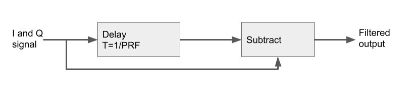
If a reflection comes from a static target ("clutter"), the two subsequent pulses will be covering each other. Subtraction will hence eliminate them.
However if a target is moving, there will be a change in amplitude from one pulse to the next due to the Doppler shift. Both reflected pulses will be different and hence will not eliminate each other.
Outcome
Normally, we see MTI plots together with the plots of previous positions as a result of tracking. In the image below, two students moved in front of the radar. One student at around 1 meter, the 2nd student at around 2 meters. In the track of MTI plots, you can well see that in moments, where the students did not move, there are no plots.
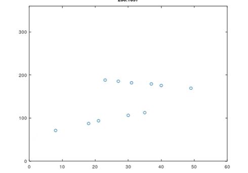 Figure: track of MTI plots
Here is a really valuable video by MIT Professor Robert M. O'Donnell for those who want to dive deep:
Moving Target Detection - how does it work?
Moving Target Detection is a newer approach to turn the moving targets visible. It is a composite algorithm.
It benefits from advancing technology of fully coherent radars and digital receivers as well as monopulse processing [radartutorial]. It consists of a set of filters:
- Doppler filter
- CFAR
- Zero velocity filter
- Clutter map subtraction
- Post processing
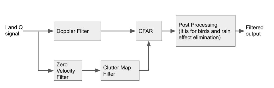
Doppler Filter
The Doppler filter compares the reflected signals of at least two pulses allowing to measure the targets radial velocity.
Below you see the 8 GHz Pulse radar in Doppler mode, showing distance and speed in the A-Scope. The image shows a hand moving in front of the radar.
CFAR
C-FAR stands for Constant False Alarm Rate.
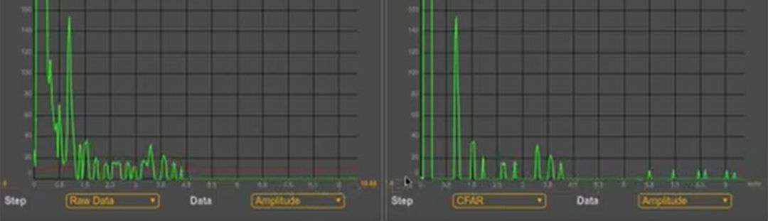
Figure: fixed threshold (left), C-FAR (right)
It is an adaptive thresholding technique to detect even weak targets against clutter.
In contrast to the static Threshold limiter, C-FAR dynamically adapts to the constellation of noise and targets at each specific point.
It uses a sliding window around a target, which calculates the mean value of neighboring reflections to determine the threshold for a specific cell under test (highlighted in green). Cells under test are called CUT. Read the main article!
Zero Velocity Filter
A zero velocity filter is a low-pass filter with the task to keep only clutter. It is a recursive filter. These filters, also called Infinite Impulse Response (IIR) filters, are an efficient way of achieving a long impulse response, without having to perform a long convolution. They execute very rapidly, but have less performance and flexibility than other digital filters.
But they fill well into the parallel branch for the clutter preparation.
Clutter Map Filter
In the 2nd step a clutter map filter averages the number of measurements over a number of scans (alternative techniques exist; read more). The advantage: even an object that stops moving for a certain time period will be detected (e.g., helicopter of drone, or a human being in search and rescue application).
The result will be added (in a weighted way) to the CFAR filter.
Post Processing
This processing allows to eliminate moving objects like birds or rain, e.g., based on reasoning such as: objects smaller than value x are eliminated.
Outcome
Let us now produce a track of plots from with the MTD filter, exactly as we did it with the MTI. In our simple setting, you will notice one difference: MTD produces also plots in moments where the students stopped (due to the clutter map). This produces a more reliable image and opens many opportunities for applications, where targets stop (even outside the ATC world).
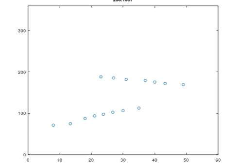 Figure: track of MTD plots
Professor Robert M. O'Donnell once more provides the possibility to gain deeper insights:
MTI and MTD in FreeScopes
MTI and MTD are part of SkyRadar's ATC module for the NextGen 8 GHz Radar. The module allows for extensive experimentation, while changing parameters and setting them in sequence with additional filters or controls.
Subsequently both can be used in the context of tracking to produce tracks and plots as required in the ICAO Doc 4444.
If you are looking for a packaged solution, MTI and MTD are part of SkyRadar's Customers' ATC Choice Package.