


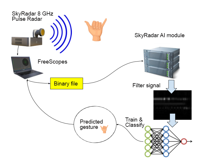
In the following we introduce a SkyRadar NextGen 8 GHz Pulse application for artificial intelligence. In this application students learn how neural networks / artificial intelligence, and especially Convolution Neural networks can be applied to perform the automatic detection of a human gesture by using RADAR technologies.
The application is off-the-shelve, and part of the Next Gen 8 GHz series. It comes with a detailed curriculum and e-Learning courses.
This hands-on training application shows that a pulse radar, which is generally considered as affordable and which can be embedded in cars or homes can be used to automatically detect human gestures. Here: finger based gestures. It is one of many applications which have been implemented by SkyRadar or which are in the process of implementation.
The application of such systems can be multiple. In a car, this can be used as an additional way of interfacing the car controls, e.g., as an alternative to voice as a UI. A given gesture would be interpreted by the on-board computer of the car as a specific command such as “put the car stereo on”, “give me latest traffic news” etc… A driver may find it easier and faster to use gestures to communicate with the car computer rather than using voice commands which are not always well interpreted by the car system.
Besides the recognition of gestures, the concept proof shows that a small pulse RADAR can be combined to a neural network engine in order to detect objects in general - not only gestures. Applications can be huge, for example insect drones could be built with micro radars and ultra low-power IoT processors such as GAP8, equipped with a Hardware convolution engine. These ‘insect’ drones (or micro-drones) could explore tunnels or caves or use radar to guide them during navigation.
 The concept proof we developed involve “standard” convolution networks such as the ones detailed here.
We used the SkyRadar 8 GHz pulse radar with the following characteristics:
- Range Resolution: better than 10 cm
- Range: up to 25 m
- Tx center frequency (ETSI): 7.29 GHz
- Tx bandwidth (ETSI): 1.4 GHz
- *Pulse Width: 0.5 nsec
- Peak Pulse output power (ETSI): -0.7 - 6.3 dBm
- Max pulse repetition frequency. 40.5 MHz
- Rx sampling rate: 23.3 GS/s
- Rx gain (ETSI): 12.3 - 15 dB
- Rx noise figure (ETSI): 5.4 - 8.8 dB
We created a backend system with keras and tensorflow and the SkyRadar AI server using flask so to have a testbed for the project. The result was that with only a few samples, mainly around 40 training units per gesture, we could obtain 80 to 100% accuracy.
Theoretical background
Pulse radar
A pulse RADAR emits small and intense signals at regular intervals. The overall signal can be represented with a very simple form as a pulse train x[n], where n is a time dependant discrete value:

The signal s is the impulse itself and can be represented by a dirac function. Eg a function that has null value except for a unique point. N is the period of the pulse.
This implies that x[n]=1 for n=dN. Here we represent the RADAR pulse train:

The principle of a RADAR is well known: it consists in sending a wave through an emitter and capturing the response wave, reflected by the bodies around using a receiver. In the RADAR we use, the emitter and the receiver are located in two different parts.
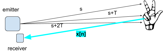
In the above diagram, a pulse s is emitted at T=0, then after a time duration of T=N, a new pulse s is emitted and then, after a time duration of T=2N, another third pulse is emitted and so on …
In this system, the ![]() pulse s is emitted at T=kN
pulse s is emitted at T=kN
If we represent the pulse train via Discrete Fourier we have:
.png?width=177&name=chart%20(2).png)
In such case .png?width=71&name=chart%20(3).png) .
.
In a RADAR there is no “response” signal from the body. The RADAR signal is a loop that originates from the RADAR emitter and ends with the RADAR receiver.
Reflected Waves and Multipath
If we name the pulse train as a function of time t : .png?width=155&name=chart%20(4).png)
Where:
- N is the number of emitted pulses;
- d is the pulse interval.
The reflected wave ![]() for one pulse is of course more complex.
for one pulse is of course more complex.
Say .png?width=173&name=chart%20(6).png)
Where:
- L= number of multipaths (eg ghost bodies that forward a return signal) ;
.png?width=21&name=chart%20(7).png) = amplitude of the a-path;
= amplitude of the a-path;.png?width=16&name=chart%20(8).png) = propagation delay of the a-path.
= propagation delay of the a-path.
![]() ‘fires’ a signal with an amplitude of
‘fires’ a signal with an amplitude of ![]() at the time t=
at the time t=![]()
This reflection acts in fact as a linear signal filter, since the reflected signal is the signal returned to the RADAR.
Finally we have a general formula for the received signal by the RADAR:
.png?width=285&name=chart%20(9).png)
where:
.png?width=28&name=chart%20(10).png) = noise (parasite from other sources).
= noise (parasite from other sources)..png?width=31&name=chart%20(11).png) =amplitude of the filter for the a-path for the k^th impulse.
=amplitude of the filter for the a-path for the k^th impulse..png?width=25&name=chart%20(12).png) = propagation delay for the a-path for the k^th impulse.
= propagation delay for the a-path for the k^th impulse.- s’=s ‘filtered’ (eg s through the multipath linear ‘filter’
.png?width=12&name=chart%20(5).png) )
)
To explain this, we must explain the concept of multipath.
When the pulse is sent at a time t=T, it is located “inside a cone” originating at the radar emitter.
If an object is located at distance d then the reflected signal - say ![]() is ‘fired’ at t= T+d/c where c is the speed of light in vacuum (~ speed of light in atmosphere) . The object is detected because it is inside a cone where the impulses will collide or not with it.
is ‘fired’ at t= T+d/c where c is the speed of light in vacuum (~ speed of light in atmosphere) . The object is detected because it is inside a cone where the impulses will collide or not with it.
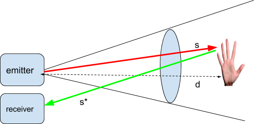
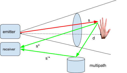
In the above diagrams, the signal is either directly reflected or reflected through a series of intermediary relays, which is the multipath.
Additionally there is background noise coming for other sources around which are necessarily linked with the RADAR emitter.
Signal Filtering
Gaussian Average
As we saw before a signal of such nature can be processed to detect objects, one must filter it. First to remove background noise, then eventually to remove effects of multipath because this gives unwanted signatures.
There are many techniques for signal filtering.Some can be very complex and involve mathematical theories such as complex analysis or Harmonic analysis. A very widely used filter is the Kalman filter.
In our experiment,we won’t use a complicated filter, but instead a basic statistical filter, the ‘Gaussian’ Average defined as such:
if we have a vector .png?width=65&name=chart%20(14).png) , we can define a trade-off variable
, we can define a trade-off variable .png?width=71&name=chart%20(15).png) and compute an average
and compute an average ![]() by
by .png?width=180&name=chart%20(20).png) .
.
And making .png?width=61&name=chart%20(18).png)
We can get an other formula for ![]() since
since
.png?width=214&name=chart%20(21).png)
…
.png?width=299&name=chart%20(22).png)
.png?width=421&name=chart%20(23).png)
…
.png?width=485&name=chart%20(24).png)
.png?width=348&name=chart%20(25).png)
Therefore, if .png?width=62&name=chart%20(14).png) are the amplitudes for the times 1...n , we transform the amplitude vector into a new amplitude vector
are the amplitudes for the times 1...n , we transform the amplitude vector into a new amplitude vector .png?width=136&name=chart%20(26).png) . here we show the efficiency of such a filter:
. here we show the efficiency of such a filter:
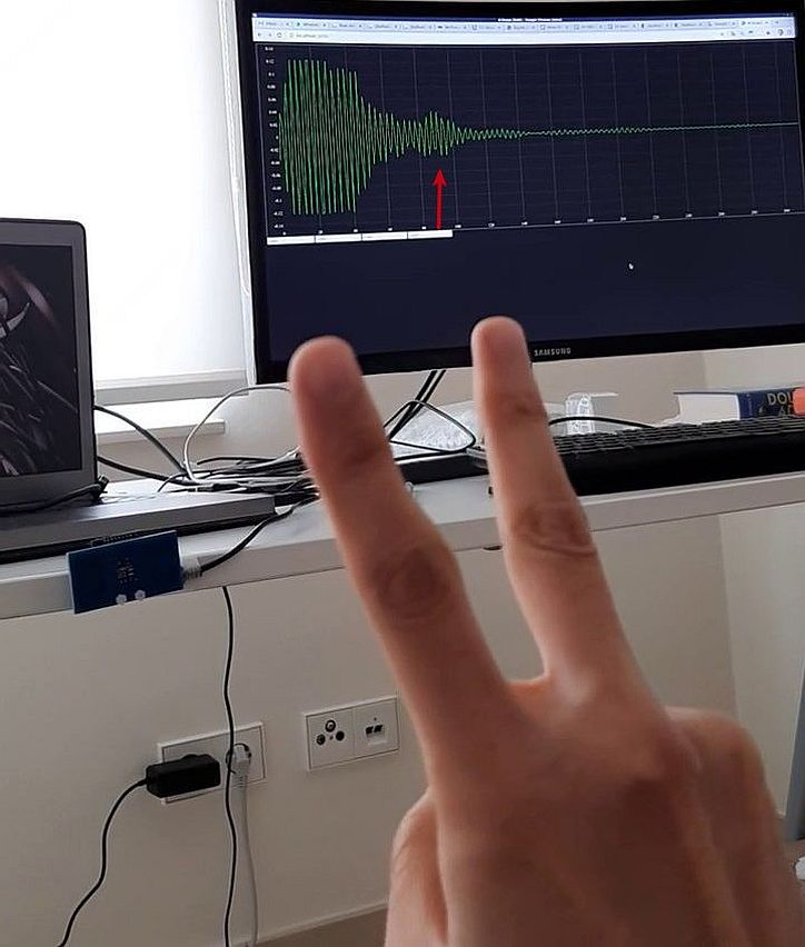
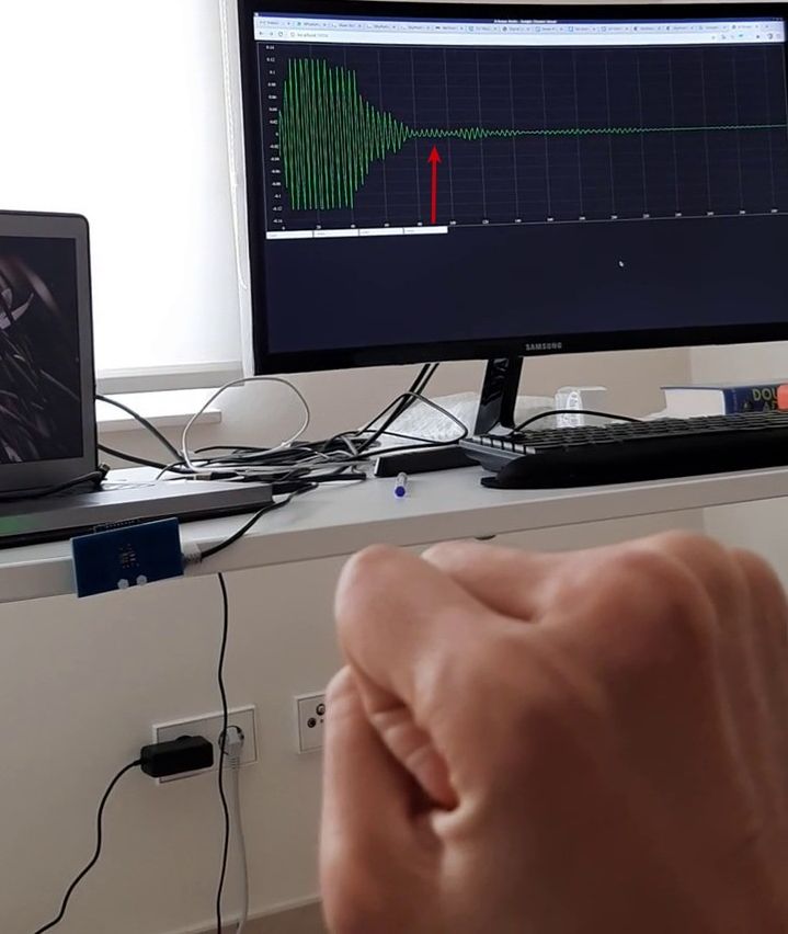
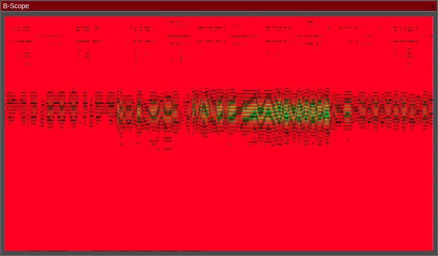
We capture a human gesture in front of the radar in what follows and we analyze and process the corresponding RADAR data.
BEFORE PROCESSING ( range number 100 /time)
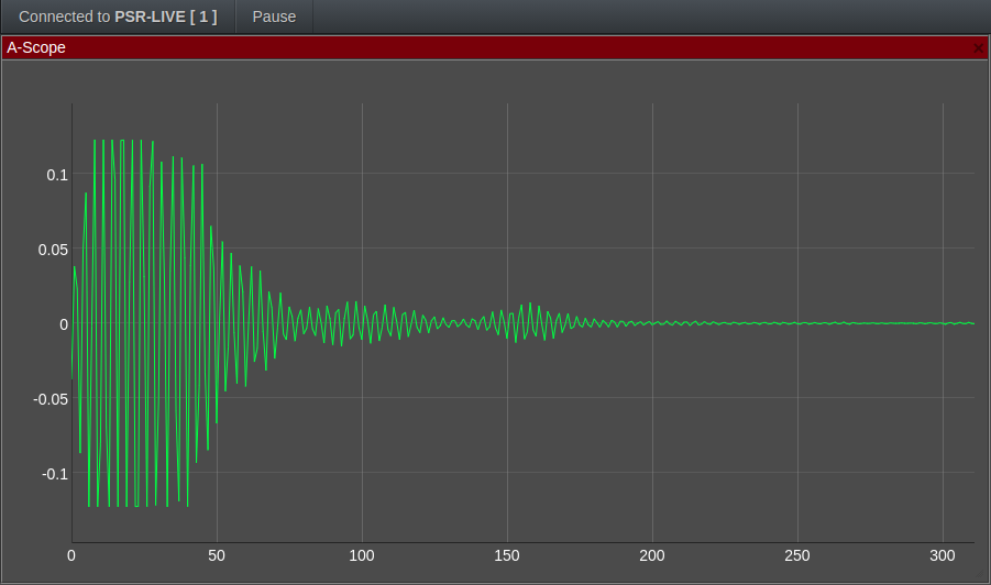
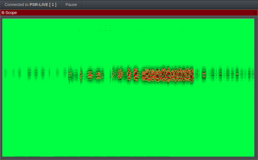
AFTER PROCESSING ( range number 100 /time)
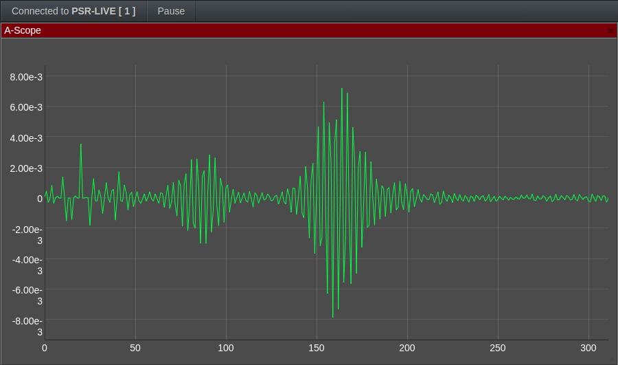
As we see on one of the frames, the filter removed most of the signal noise, revealing the real variating signal.
Fast Time / Slow Time Normalization
Next we combine low-pass signals into a m x n matrix where m represents the slow time and n represents the fast time. In the next diagrams, we show the results of Gaussian average on the matrix:
BEFORE PROCESSING
AFTER PROCESSING
We normalize the 2D Fast-Time/Slow-Time matrix by computing its mean and standard deviation.
.png?width=311&name=chart%20(27).png)
So we can simply compute the mean for each row and then the mean of the partial means.
.png?width=437&name=chart%20(28).png)
The same for the standard deviation, we can simply compute the mean of the quadratic mean of each row
AFTER NORMALIZATION
As a grayscale image:
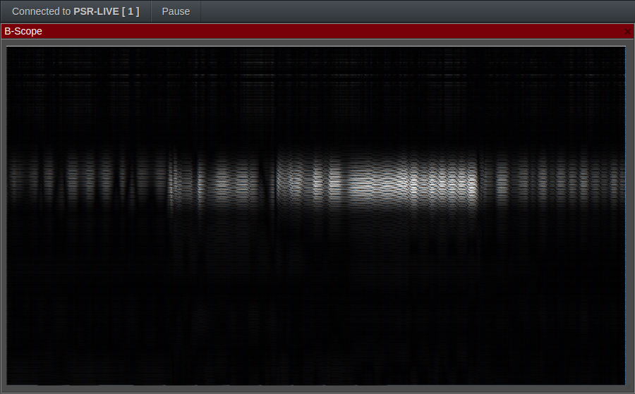
Here we can see that the grayscale image can give us a pattern in terms of object category.
We will use this approach to classify a finger-based human gesture.
Classification using a CNN
Once the signal of the RADAR have been filtered and converted into grayscale images, we will use a convolution engine to classify it.
The motivation is that convolution neural networks (CNN) are unbeatable at classifying images and they can detect patterns where the human eye sees only noise and cloudy pixels!
We will use a convolutional neural network not very different of the LeNet-1 engine.
Our convolutional network will have more convolution layers anyway but the principle is roughly the same.
At this level, the CNN can be called a Deep Learning System because it has enough layers and complexity.
Here is the Convolutional Neural Network that we will be using:
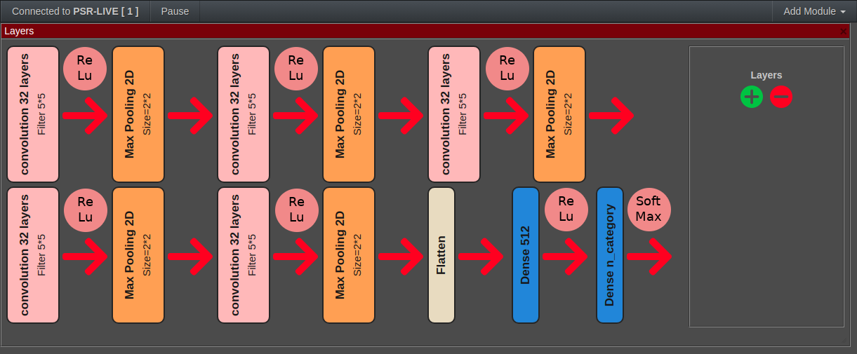
We design it with the visual CNN modeler:
The CNN we use is very common and for each hidden layer the group of operations are :
- Convolution
- ReLu
- max pooling
There is a possibility to change the modelling of the CNN. Design of a CNN should respect certain rules and take care of the conditions of the problem. The convolution layers will reveal local characteristics of the image while the relu and the max pooling layers will normalize and filter these characteristics. The final step is to have a dense looking at all the characteristics and making a final choice among the n categories to choose.
Concrete implementation
Overall principle
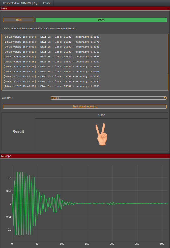
For the implementation of the concept proof, the RADAR operator will follow a given protocol to build a training and a testing set. The finger gestures are coded as such:
|
code |
gesture |
|
00000 |
|
|
10001 |
|
|
10000 |
|
|
01100 |
|


For a given gesture the RADAR operator will produce a binary file with exactly 400 frames, meaning that the recording was done through a timing where exactly 400 frames of the radar signals were received back.
These files are then processed and converted into a 2D array of decimal numbers which represents the amplitude. That array is then processed by the aforementioned signal filters and then a gray-scale is produced.
When all the training data is created, this is converted into a series of grayscales images which are in turn fed to the CNN classifier for training.
Once the classifier has been trained, the process of detection can start:
The operator scans a gesture through the RADAR, sends the sample to the server which uses the CNN to classify it and then returns the result.
Implementation
Our system is based on tensorFlow and keras for the neural network part. It is operated through SkyRadar's FreeScopes that communicates with the SkyRadar AI server. The server is creating a Flask REST service to propose the methods needed:
- Creation of the project
- Uploading training sets
- Classifying
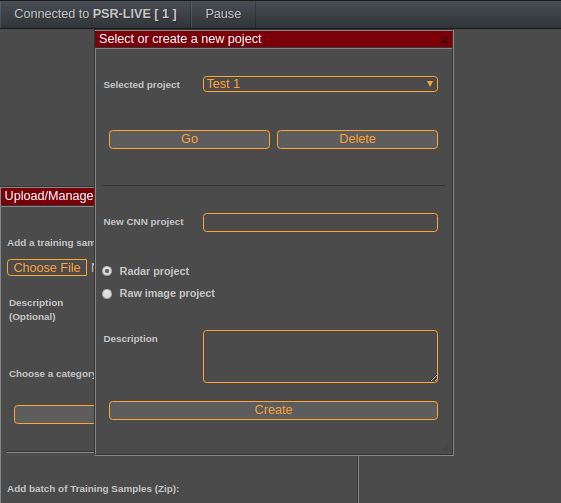
FreeScopes works by registering a user with a unique ID and allowing him to create multiple projects.
Once the user is logged in, it is possible to open an existing project or to create a new one. Each project can be a raw image classification or a specific radar classification training. A raw image classification will only use the CNN without any image filtering. This can be used to check the accuracy of the CNN on general classes of images like handwritten digits or geometrical motives for example.
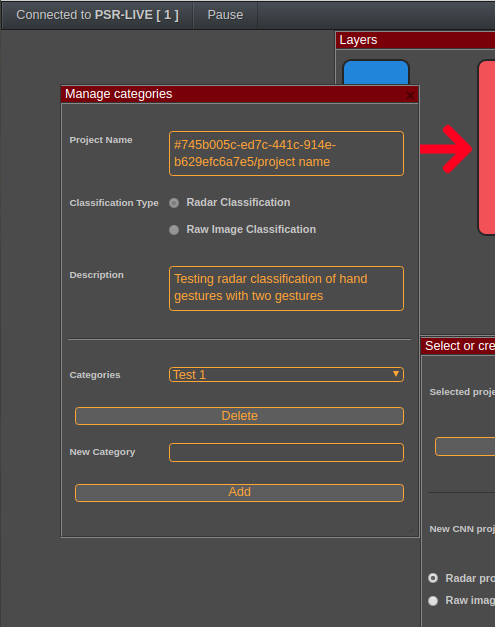
Once this is done, the user can define categories, here we define the finger gesture categories that we previously mentioned,
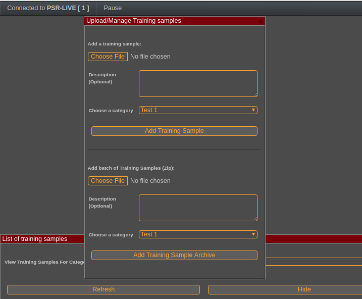
Here we show how to upload an archive containing multiples recordings
The system allows to list the samples that have been registered for training. These are the RADAR data filtered and converted into gray-scale, ready for training:
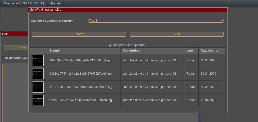
Once this is done and we have uploaded enough samples, we can train the classifier. This may take a long time and the UI will synchronously and continuously update the progress. Typically this will last around 15 minutes.
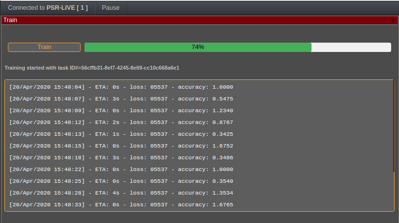
At the end of the training, the classifier will reach an accuracy level of 80 to 100%. That accuracy is determined because the classifier will split the training into a pure training data-set and a self-testing data-set which will be used to determine its accuracy at every step of the training.
This is the final step! We can check the validity of the classifier with a new image. It is immediately recognized as the right gesture.
Conclusion
With that simple but efficient experiment we see how powerful are the classifiers and that even a simple neural network (as per the standards of 2020) can allow to classify complex radar imagery. Of course hand gestures are not extremely difficult to classify and classifying other objects may be a real challenge and involve more complex designs and more powerful filters but the concept proof is achieved.
With the fact that pulse radars are now quite small and that there exist low-power processors with built-in CNN in the hardware, we can imagine many applications in Air Traffic Control or industrial applications. One of them is to provide an “electronic eye” for blind people for instance or for displacement in environments without light (speleology etc…)
We will provide many more interesting and pedagogically backed applications in this series.

Other Sources and References
- This article uses some data from the following research paper:
Hand-Based Gesture Recognition for Vehicular Applications Using IR-UWB Radar (2017), by Faheem Khan, Seong Kyu Leem, and Sung Ho Cho - More articles on artificial intelligence (2019 - today), by Martin Rupp, Ulrich Scholten, Dawn Turner and more