


A waveguide is a structure designed to confine and guide electromagnetic waves, typically in the microwave frequency range. It can be considered a hollow metal tube that serves as a low-loss transmission line for high-frequency signals.
The shape of the waveguide is chosen based on the frequency range of the signal, and it is usually rectangular, circular, or elliptical. The walls of the waveguide are typically made of a good conductor, such as copper or aluminum, to prevent any energy loss due to reflection or absorption.
Waveguides are a type of transmission media used to transmit electromagnetic signals in microwave frequency ranges. Waveguides are used in many applications, including air traffic control, military, and medical systems.
Waveguide Structure
The basic sections of a waveguide structure are as follows
The Entry section
This section is where the wave enters the waveguide. It can be rectangular, circular, or elliptical, and its dimensions determine the operating frequency range of the waveguide.
The Main section
This is the core of the waveguide and is where the wave travels the longest distance.
The Orthogonal or Transverse section
This is the transition between the main section and the output section. It is used to change the direction of the wave, typically at a right angle.
The Output section
This is where the wave exits the waveguide. The shape and size of the output section determine the wave's radiation pattern.
Types of waveguides and description of each
There are several types of waveguides, including
Rectangular waveguide
This is the most common type of waveguide and is used for high-frequency signals. It consists of a rectangular metal cavity that supports the propagation of electromagnetic waves.
Figure: Rectangular Waveguide
Circular waveguide
This type of waveguide is used for lower-frequency signals and has a circular cross-section. It provides better phase stability compared to rectangular waveguides.
Coaxial waveguide
This waveguide consists of an inner conductor surrounded by a dielectric material and an outer conductor. It is used for high-frequency signals and is typically found in microwave applications.
Dielectric waveguide
This waveguide is made of a dielectric material and does not have a metal conductor. It is used for high-frequency signals and is particularly useful for applications where a low-loss, low-dispersion waveguide is required.
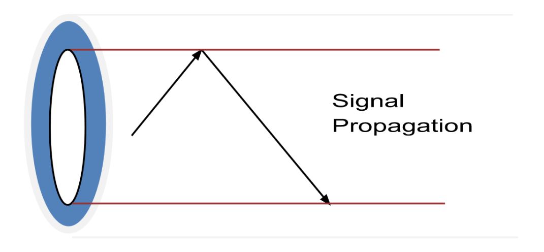
Figure: Circular-dielectric-waveguide
Optical waveguide
This waveguide uses optical fibers made of glass or plastic to guide light signals. It is used for high-speed optical communication systems.
Each type of waveguide has unique properties and characteristics that make it suitable for specific applications. The choice of waveguide depends on the frequency range, signal power, and the desired level of performance.
Signal Propagation through Waveguide
The waveguide structure is usually designed to minimize loss, reflection, and impedance mismatch. The waveguide walls are usually made of a good conductor, such as copper or aluminum, to prevent any energy loss due to reflection or absorption.
Signal transmission in a waveguide takes place through the propagation of electromagnetic waves within a confined structure made of a metal or dielectric material. The waveguide acts as a conductor for the electromagnetic waves, guiding them from the source to the destination. The waveguide is designed to have a specific dimension, which determines the frequency range it can support. When a signal is applied at one end of the waveguide, it creates an electromagnetic wave that travels through the waveguide and emerges at the other end. The waveguide provides a controlled environment for the signal to travel, reducing interference from external sources and minimizing signal loss.
Reason for the occurrence of waveguide Error
Errors in waveguide transmission can occur due to various reasons, including:
Impedance mismatches
Discontinuities in the waveguide, such as bends or junctions, can cause impedance mismatches that can reflect some of the transmitted energy to the source, causing signal loss or degradation.
Leakage
Waveguides can have leaks, either from physical defects or improper installation, which can cause signal loss or degradation.
Resonance
Waveguides can exhibit resonant behavior at specific frequencies, which can cause signal reflections, signal loss, or signal distortion.
Dispersion
Waveguides can introduce dispersion, which causes the different frequency components of the signal to travel at different speeds, causing signal distortion.
Scattering
Waveguides can scatter the transmitted signal, causing signal loss and degradation.
Mode conversion
which occurs when a waveguide supports multiple modes of propagation and the signal can get converted from one mode to another, leading to signal loss or distortion.
To minimize the impact of these errors, it is important to use high-quality waveguides, perform regular maintenance and testing, and follow established installation and operating procedures. Additionally, digital signal processing techniques, such as equalization and error correction, can be used to mitigate the effects of transmission errors in waveguides.
Examples of waveguide transmission media errors include
Mode cutoff (loss of signal in higher frequency modes)
The waveguide mode cutoff is the frequency above which a particular mode of wave propagation is no longer supported by the waveguide. In other words, it is the highest frequency at which a waveguide can effectively confine and guide a wave. When the frequency of the signal exceeds the cutoff frequency of a particular mode, the wave begins to leak out of the waveguide and the signal starts to weaken or is completely lost.
This cutoff frequency is dependent on the dimensions of the waveguide and the shape of the waveguide mode. For example, in a rectangular waveguide, the TE10 mode has the lowest cutoff frequency, and as the mode number increases, the cutoff frequency also increases. This results in a loss of signal in higher frequency modes, as they are not supported by the waveguide.
The waveguide mode cutoff is an important design consideration for waveguide-based systems, as it determines the operating frequency range and the maximum frequency that can be transmitted through the waveguide.
Non-uniformity in the waveguide dimensions (causing uneven distribution of energy)
Waveguide non-uniformity refers to variations or deviations in the waveguide dimensions from their nominal values, leading to an uneven distribution of energy along the waveguide. This non-uniformity can arise due to manufacturing tolerances, mechanical deformations, or thermal expansion, among other factors.
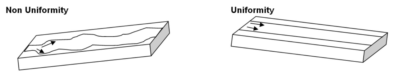
Figure: Comparing uniformity and non-uniformity in waveguide dimensions
Non-uniformities in the waveguide dimensions cause the wave to propagate unevenly, leading to changes in the wave's phase and amplitude. This, in turn, can result in reflections, power losses, and phase mismatches, which can degrade the performance of waveguide-based systems.
To minimize the effects of waveguide non-uniformity, the waveguide dimensions are carefully controlled during manufacturing and installation. High-precision manufacturing techniques and tight tolerance specifications are used to ensure that the waveguide dimensions are within acceptable limits. The waveguide is also carefully installed and maintained to prevent any deformation or mechanical damage that may cause non-uniformities.
Mode conversion (transformation of one mode into another)
Waveguide mode conversion refers to the transformation of one mode of wave propagation into another mode within a waveguide. This can occur when the wave encounters a region of non-uniformity in the waveguide dimensions, such as a bend, taper, or discontinuity in the waveguide walls. The change in the waveguide dimensions causes a change in the wave's phase and amplitude, which can result in the transformation of one mode into another.
Waveguide mode conversion is a critical issue in waveguide-based systems, as it can lead to significant power losses, phase mismatches, and other forms of signal degradation. The transformation of one mode into another can also result in the generation of unwanted modes, which can interfere with the desired signal.
To minimize the effects of mode conversion, waveguide-based systems are designed and fabricated with tight tolerance specifications and high-precision manufacturing techniques. The waveguide is also carefully installed and maintained to prevent any non-uniformities that may cause mode conversion. Additionally, mode converters and mode transformers can be used to deliberately convert one mode into another, enabling the use of waveguides for different frequency bands or to match the waveguide to a different transmission line.
Standing waves (oscillation of electromagnetic energy in the waveguide)
Waveguide standing waves, also known as standing wave patterns, are the result of the interference between two waves with equal frequency and opposite phases, which results in an oscillation of electromagnetic energy within a waveguide. In other words, the energy in the waveguide oscillates back and forth between two fixed positions, instead of propagating along the waveguide.
Standing waves are caused by a combination of reflections and transmission of energy within the waveguide, and they arise when the waveguide is mismatched to the load at its output, or when there is a discontinuity in the waveguide that causes reflections.
Standing waves can have a significant impact on the performance of waveguide-based systems, as they result in a reduction of the transmitted power and an increase in the reflection coefficient. Standing waves can also result in the formation of hotspots, which are areas in the waveguide where the electric field strength is particularly high. These hot spots can lead to increased power losses and even permanent damage to the waveguide or the components connected to it.
To minimize the effects of standing waves, waveguide-based systems are designed and fabricated with tight tolerance specifications and high-precision manufacturing techniques and are carefully matched to the load at their output. The waveguide is also carefully installed and maintained to prevent any discontinuities that may cause reflections.
Impact on Air Traffic Control Services
The impact of these errors on air traffic control services can be significant as they can cause communication delays or errors in the transmission of data and signals, leading to potential safety concerns for aircraft and passengers.
Errors in waveguide media can have a significant impact on air traffic control services. Waveguide media refers to the communication systems that are used to transmit information between air traffic control (ATC) centers and aircraft. If there are errors in the waveguide media, the transmission of critical information such as altitude, position, and flight plans may be impacted, leading to miscommunication and potential safety hazards in the airspace. In some cases, errors in waveguide media may cause complete failures in communication systems, leading to ground stops, flight delays, and rerouting of aircraft. This can result in significant operational disruptions, causing financial losses and impacting passenger confidence. To minimize the impact of waveguide media errors, it is important to have robust backup systems in place and to regularly monitor and maintain the communication systems used in air traffic control services.
Rectification of waveguide transmission Media Errors
Rectification of waveguide errors refers to the process of correcting or compensating for deviations in the waveguide dimensions that cause non-uniformities and result in waveguide performance degradation. The goal of rectification is to minimize the effects of these errors and maintain the desired performance of the waveguide-based system.
Several methods can be used to rectify waveguide errors, including:
Waveguide tuning
This involves adjusting the waveguide dimensions to correct for non-uniformities and improve performance. This can be done by adding or removing material from the waveguide walls, or by using shims or tuning screws to adjust the waveguide dimensions.
Waveguide matching
This involves matching the waveguide to the load at its output to minimize reflections and reduce the formation of standing waves. This can be done by using a matching network, such as an impedance transformer or a stub tuner, to match the waveguide impedance to the load impedance.
Mode conversion
This involves deliberately converting one mode into another, which can help to reduce the effects of mode conversion and improve system performance. Mode converters and mode transformers can be used to perform this conversion.
Waveguide inspection and repair
This involves inspecting the waveguide for discontinuities and other types of damage and repairing any defects that are found.
By implementing one or more of these methods, it is possible to correct waveguide errors and maintain the desired performance of the waveguide-based system.
Prevention of Waveguide Transmission Media Errors
Prevention of waveguide transmission media errors involves taking steps to minimize the occurrence of non-uniformities and other types of performance degradation that can occur in waveguide-based systems. The following are some methods for preventing waveguide transmission media errors:
Manufacturing tolerance control
Tight tolerance specifications and high-precision manufacturing techniques are used to ensure that the waveguide dimensions are within acceptable limits, and to minimize the effects of non-uniformities.
Installation and maintenance
The waveguide is carefully installed and maintained to prevent any deformation or mechanical damage that may cause non-uniformities.
Matching the waveguide to the load
The waveguide is matched to the load at its output to minimize reflections and reduce the formation of standing waves. This can be done by using a matching network, such as an impedance transformer or a stub tuner.
Mode conversion
Mode converters and mode transformers can be used to deliberately convert one mode into another, which can help to reduce the effects of mode conversion and improve system performance.
Inspection and repair
The waveguide is inspected periodically for discontinuities and other types of damage and repaired as necessary.
Research Highlights
Research in this field focuses on improving the design, construction, and maintenance of waveguide systems to reduce the impact of transmission media errors and improve the reliability of data and signal transmission in air traffic control services.
SkyRadar's System Monitoring & Control Solution
SkyRadar is continuously embracing new trends in its system monitoring & control solution. The Use-cases on errors and system malfunctions, described in this series are or will be implemented in SkyRadar's SkySMC training system. Implementations are consisting of
- real hardware like training radars, transmitters, receivers, UPSs, networks,
- virtualized hardware like virtual servers, networks, applications
- simulated solutions like various tower and radar designs
- or a mixture of all three
SkySMC - SkyRadar’s System Monitoring and Control Suite is a pedagogically enhanced, fully operational monitoring & control tool. We have optimized it to cater for the ATSEP-SMC training compliant to EASA's Easy Access Rules for ATM-ANS (Regulation (EU) 2017/373) and ICAO Doc 10057.
SkyRadar provides SkySMC as a complete laboratory in a turn-key approach, or as a service.
SkySMC is not a simulator, but a fully operational open monitoring system. It comes by default with a server including various virtualized applications and virtualized servers, but also connects to simulated systems. In addition, there are various hardware extensions available including training infrastructures, monitorable training radars, or even complete ATM systems, all connected to the System Monitoring & Control solution.
SkyRadar's System Monitoring & Control training system can be easily blended into distance learning solutions.
Let's talk
Stay tuned to be always the first to learn about new use cases and training solutions in radar qualification (real radars or simulators) for ATSEP.
Or simply talk to us to discuss your training solution.

Reference and Further Study
- Optical Waveguide (retrieved March 2023), by cleanenergywiki