


SkyRadar’s Radar reference architecture is a framework that describes the different components that make up a radar system, and how they interact with each other.
It is the basic configuration to provide use cases in system monitoring and control training.
Importance of Radar System Architect for ATSEP
It can be used as a tool for training Air Traffic Safety Electronics Personnel (ATSEP) on the design, operation, and maintenance of radar systems. One of the main ways that the reference architecture facilitates training is by providing a clear overview of the system. The reference architecture breaks down the radar system into its parts, such as the antenna, transmitter, receiver, signal processing unit, display unit, control unit, data link, etc. This helps ATS personnel to understand how each component contributes to the overall operation of the system. Understanding the individual components of the system also helps ATS personnel to understand how they interact with each other and how they are integrated into the system as a whole. This allows them to have a better understanding of the radar system.
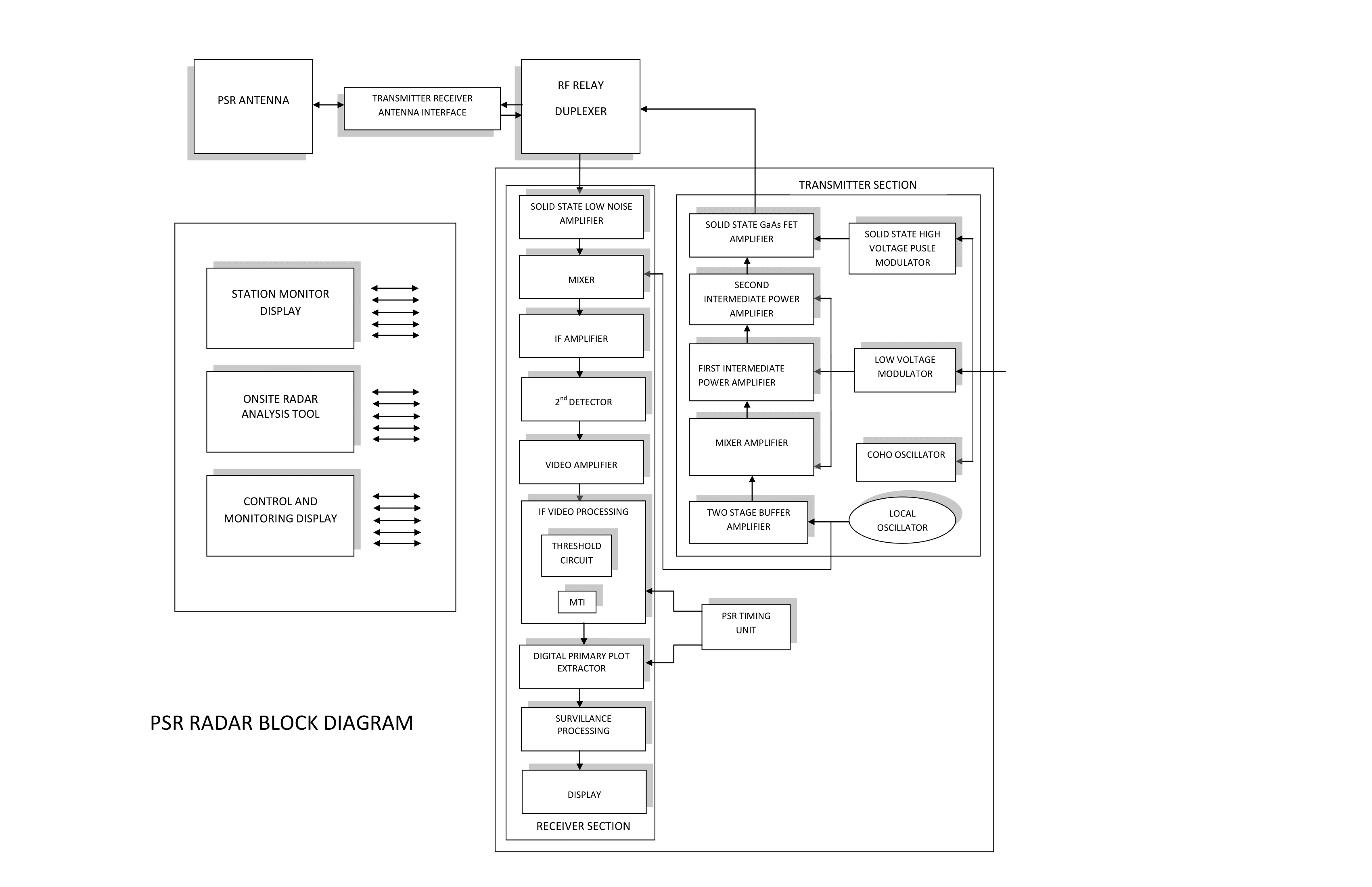
Figure: Reference Architecture (download PDF)
The reference architecture typically includes several key components, such as
Antenna
This is the device that transmits and receives radar signals. It is typically located at the top of a tower or on a mountaintop.
Transmitter
This is the device that generates the radar signals that are transmitted by the antenna. It typically includes a high-power amplifier and a frequency synthesizer.
Receiver
This is the device that detects and processes the radar signals that are received by the antenna. It typically includes a low-noise amplifier, a mixer, and a filter.
Signal Processing Unit
This is the device that processes the radar signals to extract useful information, such as the range, azimuth, and elevation of the target.
Display Unit
This is the device that presents the radar information to the operator. It typically includes a CRT or LCD screen and a user interface.
Control Unit
This is the device that controls the operation of the radar system. It typically includes a microprocessor and a set of control algorithms.
Data Link
This is the communication link that connects the radar system to other systems, such as the Air Traffic Management (ATM) system and the Automatic Dependent Surveillance-Broadcast (ADS-B) system.
The Reference Architecture Facilitates Training
The reference architecture facilitates training by providing a clear understanding of the system's functionality. The reference architecture describes the different functions that the system performs, such as signal transmission, signal reception, signal processing, and data display. It also describes the different types of data that the system can provide, such as range, azimuth, and elevation information. This helps ATS personnel to understand the types of information that the system can provide and how it can be used to support the safe and efficient operation of the airspace. ATS personnel can also learn to interpret and act upon the data provided by the radar system more effectively.
The Reference Architecture Facilitates Understanding of System Performance and Limitations
The reference architecture also facilitates training by providing a clear understanding of the system's performance and limitations. The reference architecture describes the system's range, accuracy, and update rate, as well as any limitations that may affect its performance, such as weather conditions or interference from other systems. This helps ATS personnel to understand the system's capabilities and limitations, and to make informed decisions about how to use the system to support the safe and efficient operation of the airspace.
Let us discuss now all of the elements in the block diagram of the radar system.
Antenna
Description of Primary Surveillance Radar Antenna
PSR (Primary Surveillance Radar) antenna is a type of radar antenna that is used to detect and track aircraft at long ranges. These antennas are typically located at the top of a tower or on a mountaintop and use high-powered microwave signals to detect and track aircraft over long distances.
Typical Shape of PSR Antenna
PSR antennas typically use a parabolic dish shape, which focuses the transmitted and received microwave signals in a narrow beam. This allows the antenna to detect aircraft at long ranges while still maintaining a high degree of accuracy. The antenna is usually mounted on a motorized pedestal that allows it to rotate and scan the airspace around it.
Types of PSR Antennas
There are several types of PSR antennas available, each designed for specific applications and environments. Some PSR antennas are designed for long-range surveillance, while others are designed for short-range tracking. There are two main types of PSR antennas, mechanical and electronic PSR. The mechanical PSR uses a motor to rotate the dish, while the electronic PSR uses electronic beam steering to steer the radar beam. Electronic PSR is considered more efficient and precise than mechanical PSR.
Importance of PSR Antenna in Air Traffic Control Services
The PSR antenna is a critical component of an ATC system that plays a vital role in ensuring the safety and efficiency of the airspace by providing a primary means of detecting and tracking aircraft at long ranges. The accuracy and reliability of the PSR antenna are essential for the safe operation of the airspace, and regular maintenance and calibration of the antenna are crucial to ensure its proper functioning. The data provided by the PSR antenna is used by ATC personnel to identify and track aircraft and to make decisions about how to safely and efficiently manage airspace.
X-band or S-band frequencies
A PSR (Pulse-Doppler Surveillance Radar) antenna is a type of antenna used in radar systems for surveillance and tracking of aircraft and other moving targets. The PSR antenna is designed to transmit and receive radar signals in the X-band or S-band frequencies, typically between 8 GHz and 12 GHz.
Physical Structure of Antenna
The physical structure of a PSR antenna typically includes a reflector and a feed horn. The reflector is a large, dish-shaped surface that focuses the radar energy into a beam, while the feed horn is a small device that sends and receives the radar signals. The reflector is typically made of metal, such as aluminum, and is shaped to optimize the radar beam pattern.
Electronic Structure of Antenna
The electronic structure of a PSR antenna includes a waveguide, a transmitter, and a receiver. The waveguide connects the feed horn to the transmitter and receiver and is used to guide the radar signals to and from the antenna. The transmitter generates the radar signals, while the receiver detects and processes the reflected signals.
The function of PSR Antenna
The function of a PSR antenna is to transmit and receive radar signals to detect and track aircraft and other moving targets. The PSR antenna uses the Doppler Effect to measure the radial velocity of the target, which allows the radar system to distinguish between stationary and moving targets.
Research Highlights Regarding PSR Antenna
Research in this field is focused on developing more compact, lightweight, and efficient PSR antennas, as well as improving the performance and accuracy of the radar signals. Additionally, recent research focuses on integrating machine learning techniques into the PSR antenna to improve target detection and tracking capabilities.
Transmitter-Receiver Antenna Interface
What is the transmitter-Receiver Antenna Interface?
The radar Transmitter-Receiver Antenna Interface is the point where the transmitter and receiver of a radar system are connected to the antenna. The transmitter generates the high-powered radio frequency (RF) signals that are sent out by the antenna, while the receiver detects and processes the signals that are received by the antenna.
Utilization of the Same Antenna for Transmission and Reception
The interface is typically implemented using a duplexer, which is a device that allows the transmitter and receiver to share the same antenna. The duplexer uses filters and switches to separate the transmitted and received signals and to direct them to the appropriate components of the system. The duplexer also ensures that the transmitter and receiver are operating at the correct frequency and that the transmitted and received signals are properly aligned.
Other Components and Signal Strength
The radar Transmitter-Receiver Antenna Interface may also include other components such as amplifiers, frequency synthesizers, and mixers. These components are used to optimize the performance of the system and to ensure that the transmitted and received signals are of sufficient strength and quality.
Logic Diagram of Transmitter- Receiver Antenna Interface
The logic diagram of a Transmitter-Receiver Antenna Interface typically includes input and output stages, a power amplifier, and a duplexer
Electronic Structure of Transmitter-Receiver Antenna Interface
The electronic structure of a Transmitter-Receiver Antenna Interface includes components such as transistors, diodes, and capacitors.
The function of the Transmitter-Receiver Antenna Interface
The function of a TRAI is to allow the transmitter and receiver to share the same antenna while preventing interference between the two.
How the Operation of the Transmitter-Receiver Antenna Interface is controlled
The operation of a Transmitter-Receiver Antenna Interface is typically controlled by a microcontroller, which manages the switching between the transmitter and receiver modes and adjusts the power levels as needed.
Research Highlights Regarding Transmitter-Receiver Antenna Interface
Research in the area of transmitter-receiver antenna interfaces in 2022 is focused on developing new technologies to improve the performance and efficiency of wireless communication systems. Some of the key areas of research include
Antenna array design Researchers are exploring new ways to design and optimize antenna arrays to improve the gain, directivity, and beam-forming capabilities of wireless systems.
Beamforming techniques
Researchers are developing new beam-forming techniques to enhance the performance of antenna arrays and improve the efficiency of wireless communication systems.
Massive MIMO
Research is being conducted on Massive MIMO (Multiple Input Multiple Output) systems, which use large antenna arrays to improve the capacity and coverage of wireless networks.
Reconfigurable Antennas
Researchers are exploring the use of reconfigurable antennas, which can change their radiation patterns in response to changing conditions, to improve the performance and efficiency of wireless systems.
Millimeter-wave
With the increasing demand for high-bandwidth wireless communication systems, researchers are studying the potential use of millimeter-wave frequencies for wireless communications and developing new technologies to support this frequency band.
Artificial Intelligence
Artificial intelligence techniques are being researched to optimize the performance of wireless communication systems and improve the efficiency of the transmitter-receiver antenna interface.
The goal of this research is to develop new technologies that can enhance the performance and efficiency of wireless communication systems, making them faster, more reliable, and more capable of handling large amounts of data.
RF Relay Duplexer
What is RF Relay Duplexer
An RF Relay Duplexer is a device that allows the simultaneous transmission and reception of radio frequency (RF) signals in a single antenna system. It is used in communication systems such as mobile phones, radios, and base stations to separate the transmitted and received signals, allowing for full-duplex communication.
What is the Logic Diagram of the RF Relay Duplexer
The logic diagram of an RF relay duplexer typically includes two RF relays, a transmit/receive (T/R) switch, and a duplexer filter. The RF relays are used to switch the antenna between transmit and receive modes, while the T/R switch is used to switch the RF signal path between the transmitter and receiver. The duplexer filter is used to separate the transmitted and received signals by frequency, allowing the transmitter and receiver to operate on different frequencies without interference.
What is the Electronic Structure of the RF Relay Duplexer
The electronic structure of an RF relay duplexer typically includes RF relays, a T/R switch, a duplexer filter, and other passive components such as capacitors, inductors, and resistors. The RF relays and T/R switch are typically made of semiconductor materials such as silicon or gallium arsenide, while the duplexer filter is typically made of ceramic or LC (inductor-capacitor) resonators.
What is the Function of the RF Relay Duplexer
The function of an RF relay duplexer is to allow the simultaneous transmission and reception of RF signals in a single antenna system by separating the transmitted and received signals by frequency. It uses RF relays, a T/R switch, and a duplexer filter to switch the antenna between transmit and receive modes, switch the RF signal path between the transmitter and receiver, and separate the transmitted and received signals by frequency respectively.
How RF Relay Duplexer Operates
The operation of an RF relay duplexer is based on the principle of frequency separation. When the system is in the transmit mode, the RF relays switch the antenna to the transmitter and the T/R switch connects the transmitter to the antenna. The duplexer filter prevents the transmitted signal from reaching the receiver by passing only the desired frequency band to the transmitter and blocking the rest. When the system is in the receive mode, the RF relays switch the antenna to the receiver and the T/R switch connects the receiver to the antenna. The duplexer filter prevents the received signal from reaching the transmitter by passing only the desired frequency band to the receiver and blocking the rest.
Research Highlights Regarding RF Relay Duplexer
Research on RF relay duplexers has focused on developing new materials, structures, and fabrication methods to improve their Performance.
Solid State Low Noise Amplifier
What is a Solid State Low Noise Amplifier?
A radar solid state low noise amplifier (LNA) is an electronic device used to amplify weak radar signals while minimizing the amount of unwanted noise that is also amplified. It is a critical component in radar systems, as it improves the sensitivity and resolution of the system by amplifying the weak signals before they are processed.
Logic Diagram of Solid State Low Noise Amplifier
The logic diagram of a radar solid state LNA shows the different components and their connections. The electronic structure of the LNA typically includes transistors and other active devices, as well as passive components such as resistors, capacitors, and inductors.
The Function of Solid State Low Noise Amplifier
The function of the radar solid state LNA is to amplify the weak radar signals while minimizing the amount of noise that is also amplified. This is typically accomplished by using active devices with low noise figures and by carefully designing the circuit to minimize the amount of noise that is generated.
How Does Solid State Low Noise Amplifier Operates
The operation of a solid-state LNA is based on the principles of electronic amplification using semiconductor devices, such as transistors. Several types of transistors can be used in an LNA, including bipolar transistors, field-effect transistors (FETs), and high electron mobility transistors (HEMTs).
The input signal is typically applied to the gate or base of the transistor, which is followed by the amplification process. The amplified signal is then taken from the drain or collector of the transistor. To achieve low noise, the amplifier should be designed to have a low input voltage noise and low current noise.
The LNA typically consists of multiple stages of amplification, each stage providing a small amount of gain. The gain of each stage is determined by the transistor's properties, such as its trans-conductance and noise figure, as well as the bias conditions.
The LNA is also typically designed to have a high input impedance and low output impedance, which helps to match the impedance of the input and output signals to the transistor. Additionally, LNAs are often designed to have a narrow bandwidth, to amplify only the desired frequency range.
The device is also designed with noise reduction methods such as input matching, output matching, and feedback. The noise figure, which is a measure of the noise added by the amplifier to the signal, is typically less than 1 dB, which allows for a high signal-to-noise ratio.
How Signal Flow takes place in Solid State Low Noise Amplifier
The signal flow in a radar solid state LNA begins with the weak radar signal being input into the LNA. The signal then passes through one or more stages of active devices such as transistors, where it is amplified. The amplified signal then leaves the LNA and is passed onto the next stage of the radar system for further processing.
Research Highlights Regarding Solid State Low Noise Amplifiers
Research on solid-state low noise amplifiers (LNAs) focuses on developing new technologies and design techniques to improve the performance of LNAs in terms of gain, noise figure, linearity, and power consumption.
Some recent research highlights in solid-state LNA research include
Wideband LNAs
Researchers are developing wideband LNAs that can amplify a wide range of frequencies with high gain and low noise figures. This is important for applications such as cognitive radio and software-defined radio.
Low-power LNAs
Researchers are developing LNAs that consume less power, which is important for battery-powered devices and portable applications.
Wide Dynamic Range LNA
Researchers are developing LNAs that have high gain, low noise figure, and wide dynamic range, which is important for applications such as wideband wireless communication systems, radar systems, and satellite communication systems.
Integration of LNA
Researchers are developing ways to integrate LNA with other components such as filters, oscillators, and modulators to form a complete transceiver system on a single chip, which can reduce the size and cost of the system.
Non-linearity reduction
Researchers are working on reducing the non-linearity of LNAs, which will improve the linearity of the signal and reduce signal distortion.
Wideband balun LNA
Researchers are developing LNAs that use a wideband balun, which can improve the input matching and reduce the noise figure.
High-performance LNAs
Researchers are working on developing LNAs that can operate at high temperatures, high frequencies, and high power levels, which is important for applications such as satellite communication systems, military radar systems, and space exploration.
Mixer
What is a Mixer?
A mixer in a Pulse-Doppler radar (PSR) system is a type of non-linear electronic device that combines two signals to produce new frequencies.
Electronic Structure of Mixer
The electronic structure of a mixer typically includes diodes, transistors, or other active electronic components. The diode or a transistor is used as a mixing element The exact configuration will depend on the specific design of the radar system and the requirements of the application. The diode or transistor is biased in a way that allows it to act as a non-linear element, which is necessary for the mixing process to occur.
Function Performed by Mixer
The function of the mixer is to convert the RF signal to a different frequency, which is then used for further processing in the radar system. This allows the radar to detect targets at different ranges and to discriminate between different types of targets.
Operation of Mixer in Pulse–Doppler Radar
The operation of a mixer in a PSR radar system is typically done in two steps, the first step is down-conversion, where the radio frequency is converted to a lower frequency, and the second step is up-conversion, where the intermediate frequency is converted back to radio frequency.
Input and Output Signal of Mixer Explained
The input signals are typically a radio frequency (RF) signal and a local oscillator (LO) signal. The RF signal is typically supplied by an antenna, while the LO signal is generated by a local oscillator circuit. The LO signal is used to shift the frequency of the RF signal, allowing the radar system to operate at a different frequency than the incoming signals.
The output signal produced by the mixer is the sum and difference frequencies of the input signals. The sum frequency is the frequency at which the radar system operates, while the difference frequency is the frequency of the original RF signal. This output signal is then sent to the next stage of the radar system for further processing and analysis.
Research Highlights Regarding Mixer
Research into radar mixers has focused on improving their performance and efficiency, as well as developing new types of mixers for specific applications. For example, researchers have developed low-noise mixers that have lower levels of unwanted signals, which improves the sensitivity and accuracy of the radar system. Other research has focused on developing mixers that can operate at higher frequencies and in harsher environments, such as in high-temperature or high-radiation environments.
In recent years, there has been a focus on developing mixers using MEMS (Micro-electromechanical system) technology. These mixers are small in size, low-cost, and power-efficient and can be used in various applications like IoT, 5G, Automotive, and many more.
Second Detector
What is a Second Detector?
A second detector in a PSR system is used as a confirmatory step to improve the accuracy of the detection.
Electronic Structure of Second Detector
The electronic structure of a second detector in a PSR system would typically include a signal processing chain that includes amplifiers, filters, and comparators. The logic diagram would show the flow of the signal through these components and how they are connected to make the final detection decision.
The function of the Second Detector
The function of the second detector is to confirm the detection of a pulse signal by the primary detector, which may have a higher sensitivity but lower specificity. The second detector can use different signal processing techniques such as pulse-shape discrimination (PSD) or time-of-arrival (TOA) measurements to make a more accurate detection.
How does the Second Detector Operate
The operation of the second detector would involve receiving the signal from the primary detector, processing the signal through the electronic components, and making a final detection decision.
Research Highlights Regarding the Second Detector
Research in the area of a second detector in radar has focused on developing advanced signal-processing techniques to improve the accuracy and reliability of detection. Some of the highlights of this research include
Adaptive filtering
Researchers have developed adaptive filtering algorithms that can adapt to the changing characteristics of the signal, such as the Doppler frequency shift, to improve the performance of the second detector.
Machine learning
Machine learning techniques, such as artificial neural networks and support vector machines, have been used to improve the performance of the second detector by allowing it to learn from past detections and adapt to new situations.
Statistical signal processing
Researchers have used statistical signal processing techniques, such as maximum likelihood estimation and Bayesian filtering, to improve the performance of the second detector by making more accurate detection decisions.
MIMO radar
Multiple-input multiple-output (MIMO) radar technology has been developed to improve the range and resolution of radar systems. MIMO radar uses multiple antennas to transmit and receive signals, which can improve the performance of the second detector by providing more information about the target.
Synthetic Aperture Radar (SAR)
SAR is a method of imaging that can be used to create high-resolution images of large areas of land. SAR is used in many radar systems to create high-resolution images of the land, which can be used to detect and track targets.
Pulse-shape Discrimination (PSD)
Pulse-shape discrimination (PSD) is a signal processing technique that can be used to improve the accuracy of radar detections by analyzing the shape of the radar pulse.
These research highlights show that the second detector in radar systems is an active area of research with a variety of advanced signal processing techniques and new technologies being developed to improve the accuracy and reliability of detection.
Video Amplifier
What is a Video Amplifier?
A radar system video amplifier is a component in a radar system that amplifies the output signal from the second detector before it is sent to the signal processor. The structure of a video amplifier typically includes one or more amplifying stages, input and output connectors, and power supply connections.
The function of the Video Amplifier
The function of the video amplifier is to increase the amplitude of the output signal from the second detector so that it can be accurately processed by the signal processor. This is typically done by using one or more amplifying stages, which can be based on bipolar junction transistors (BJTs), field-effect transistors (FETs), or other types of amplifying devices.
Operation of Video Amplifier
The operation of a video amplifier is straightforward. The output signal from the second detector is applied to the input of the amplifier, and the amplified signal is then sent to the signal processor. The amplifier is designed to provide a high gain, low noise, and wide bandwidth to ensure the signal is accurately amplified.
Research Highlights Regarding Video Amplifiers
Research in video amplifiers has focused on developing new types of amplifiers that can provide higher gains, lower noise, and wider bandwidths. For example, some researchers have developed video amplifiers based on high electron mobility transistors (HEMTs) and gallium nitride (GaN) devices, which have higher gain and wider bandwidths than traditional BJT and FET-based amplifiers.
Additionally, research has also been conducted on developing video amplifiers that can operate at higher frequencies and in harsher environments, such as in high-temperature or high-radiation environments. Some research has also focused on developing power-efficient video amplifiers for portable radar systems or use in battery-powered devices.
Radar System IF Video Processor
What is a IF Video Processor?
A radar system IF (Intermediate Frequency) video processing is a component in a radar system that processes the output signal from the video amplifier before it is sent to the signal processor. The structure of an IF video processor typically includes one or more signal processing stages, input and output connectors, and power supply connections.
The function of the IF Video Processor
The function of an IF video processor is to extract useful information from the output signal from the video amplifier. The signal is typically processed through a series of stages, such as filtering, amplification, and demodulation, to extract information about the target's location, velocity, and other characteristics.
How does IF Video Processor Operates
First, the output signal from the video amplifier is passed through a band-pass filter, which removes unwanted frequency components and passes only the desired signal to the next stage.
Next, the filtered signal is amplified to increase its amplitude.
Finally, the amplified signal is demodulated to extract information about the target's location and velocity. This can be done using various demodulation techniques such as coherent, non-coherent, or quadrature detection.
Research Highlights Regarding IF Video Processor
Research in IF video processing has focused on developing new signal processing techniques that can extract more information about the target, improve the accuracy of the radar system, and reduce the number of unwanted signals. For example, researchers have developed new filtering techniques, such as adaptive filtering, to remove unwanted signals and improve the signal-to-noise ratio. Other research has focused on developing new demodulation techniques, such as pulse-Doppler processing, to extract information about the target's velocity. Additionally, researchers have also developed new methods for processing the signal in real-time and for implementation on digital signal processors (DSPs).
Recently, research has also been focused on developing techniques to process and extract information from the IF video signal that can be used for various applications like target classification, automatic tracking, and decision-making.
Threshold Circuit
What is a Threshold Circuit?
The electronic structure of a radar threshold circuit typically includes a comparator circuit, which compares the strength of the radar's received signal to a predefined threshold level. The comparator circuit is typically made up of amplifiers, resistors, and diodes, which are used to amplify the received signal and compare it to the threshold level. If the signal strength is above the threshold, the comparator circuit sends a signal to the radar's processing unit indicating the presence of a target.
The function of the Threshold Circuit
The function of a radar threshold circuit is to set a minimum level of signal strength required for the radar to detect an object. This helps to reduce noise and false signals in the radar's detection process, by only triggering a detection when the signal strength is above a certain level.
The operation of a radar threshold circuit is typically performed by the radar's processing unit, which uses algorithms to analyze the radar data and determine if an object is present. The threshold level can be adjusted to optimize the radar's performance for different scenarios and environments.
Research Highlights Regarding Threshold Circuit
Research in radar threshold circuit electronics focuses on developing new methods for setting and adjusting the threshold level to improve the radar's performance and reduce false alarms. Additionally, research is conducted on how to optimize the threshold level for different scenarios and environments. Also, the research focuses on the development of new electronic components and circuit designs to improve the sensitivity and performance of the radar threshold circuit.
Moving Target Indicator (MTI)
What is a Moving Target Indicator (MTI)?
A Moving Target Indicator (MTI) is a radar system that is used to detect and track moving objects. It is typically used in air and sea surveillance applications to detect and track aircraft, ships, and other moving targets.
The logic behind Moving Target Indicator System
The basic logic behind an MTI system is to transmit a radar signal and then receive the reflected signal. The received signal is then compared to a reference signal, which is typically a delayed version of the transmitted signal. By comparing the received signal to the reference signal, the MTI system can determine the range, velocity, and direction of movement of any moving targets.
Logic Diagram of Moving Target Indicator
-
A logic diagram for an MTI system would typically include the following components
-
A radar transmitter is used to transmit the radar signal
-
A radar receiver, which is used to receive the reflected radar signal
-
A delay line, which is used to create the reference signal
-
A comparator, which is used to compare the received signal to the reference signal
-
An indicator, which is used to display the location and movement of any moving targets detected by the system
-
The output of the comparator is then fed into a filter to suppress the stationary clutter and enhance the moving targets.
It's important to note that there are different types of MTI radar systems, with varying levels of complexity. Some systems are designed for specific applications, such as detecting low-flying aircraft or tracking fast-moving ships, while others are more general-purpose systems that can be used in a wide range of applications.
Electronic Structure of Moving Target Indicator
The electronic structure of a radar Moving Target Indicator (MTI) typically includes a receiver, a signal processing unit, and a display unit. The receiver captures the radar signals reflected by the targets and the processing unit applies the MTI algorithm to filter out stationary clutter and detect the moving targets. The display unit shows the moving targets as blips on a radar screen.
The function of the Moving Target Indicator
The function of an MTI is to filter out stationary clutter, such as buildings or terrain, and display only moving objects. The MTI system uses the difference in phase or amplitude between consecutive radar pulses to determine if an object is moving.
How Does the Moving Target Indicator Operate?
After the IF amplifier stage, the intermediate frequency (IF) signal is passed to the second detector for further processing. The second detector, also known as the demodulator, is typically used to extract the information contained in the IF signal. The operation of the second detector can include one or more of the following steps
Amplification
The IF signal is amplified to a level suitable for further processing.
Demodulation
The IF signal is demodulated to extract the original modulated radar signal. This can be done using a variety of techniques such as amplitude demodulation, frequency demodulation, or phase demodulation.
Filtering
The de-modulated signal is filtered to remove any unwanted noise or interference.
Detection
The filtered signal is then detected using a detector circuit such as a square-law detector or a coherent detector, which converts the electrical signal into a form that can be easily processed by the receiver's signal processing circuit.
The detected signal is further processed to extract the target information. This can include signal compression, pulse compression, Doppler processing, and target tracking.
Research Highlights of the Moving Target Indicator
Research in Moving Target Indicator (MTI) technology is ongoing and constantly evolving. Some of the key areas of research include
Development of advanced signal processing techniques
This aims to include techniques such as machine learning and deep learning, which can improve the ability of MTI systems to detect and track targets in complex and cluttered environments.
Development of new radar frequency bands
This can include using higher frequency bands such as millimeter wave radar, which can improve the resolution and accuracy of MTI systems.
Research in the field of cognitive radar
This aims to adapt the radar parameters to the environment and the target, to improve the performance and reduce interference.
Research in the field of wideband radar
This aims to use a wideband signal to improve the accuracy of the radar and increase the number of targets that can be detected and tracked simultaneously.
Stealth Technology
Research in the field of stealth technology, trying to develop methods to detect stealth targets that are designed to evade radar detection.
Research in the field of multiple-input multiple-output (MIMO) radar systems
Aims to improve the resolution and accuracy of MTI systems by using multiple antennas.
The research in MTI technology will continue to evolve and aim to improve the performance, accuracy, and capabilities of MTI systems for surveillance and tracking applications in various domains.
Digital Primary Plot Extractor
What is a Digital Primary Plot Extractor?
A Radar System Digital Primary Plot Extractor (DPPE) is a digital circuit that processes radar signals and extracts the primary radar plots (i.e., the locations of radar targets) for display on a radar screen.
Logic Diagram of a Digital Primary Plot Extractor
The logic diagram of a DPPE typically includes a series of digital circuits such as a Pulse Compression circuit, a matched filter, an A/D converter, a Moving Target Indicator (MTI) circuit, and a digital signal processor (DSP). These circuits work together to process the radar signals and extract the primary radar plots.
Electronic Structure of a Digital Primary Plot Extractor
The electronic structure of a DPPE typically includes a combination of digital logic gates, flip-flops, multiplexers, and other digital building blocks, as well as DSP and memory components.
The function of the Digital Primary Plot Extractor
The function of a DPPE is to process radar signals and extract the primary radar plots for display on a radar screen. It uses techniques like Pulse Compression, matched filtering, MTI, and DSP to extract the primary radar plots.
How does the Digital Primary Plot Extractor Operate
The operation of a DPPE is typically performed by the radar's processing unit, which uses algorithms to analyze the radar data and extract the primary radar plots. The extracted plots are then displayed on a radar screen.
Research Highlights Regarding the Digital Primary Plot Extractor
Research in DPPE focuses on developing new algorithms and techniques to improve the performance of the DPPE, such as reducing false alarms, increasing the accuracy of target detection, and improving the ability to detect low-flying or stealthy targets. Additionally, research is conducted on how to optimize the DPPE for different scenarios and environments, and on the development of new digital building blocks and circuit designs to improve the sensitivity and performance of the DPPE.
Surveillance Processor
What is a Surveillance Processor?
Surveillance Processor (SP) is a digital circuit or system that processes radar signals and extracts information about the location, velocity, and other characteristics of radar targets. It typically includes a combination of different processing stages such as signal detection, tracking, data fusion, and target identification.
Logic Diagram of a Surveillance Processor
A logic diagram of a Surveillance Processor may include a series of digital circuits such as a Pulse Compression circuit, a matched filter, an A/D converter, a Moving Target Indicator (MTI) circuit, a Digital Signal Processor (DSP), a tracking algorithm, and a data fusion algorithm. These circuits work together to process the radar signals and extract the target information.
Electronic Structure of a Surveillance Processor
The electronic structure of a surveillance processor refers to how the surveillance data is processed and analyzed. It typically includes several key components
Data acquisition
This component receives surveillance data from various sources, such as cameras, sensors, and other monitoring devices. The data may be in the form of video, audio, or other types of signals.
Signal processing
This component processes the surveillance data to extract relevant information, such as identifying and tracking objects, recognizing patterns, and detecting anomalies. It may include techniques such as image processing, audio processing, and machine learning.
Data storage
This component stores the processed surveillance data in a format that can be easily accessed and analyzed.
Data analysis
This component analyzes the stored surveillance data to identify patterns, trends, and anomalies. It may include techniques such as data mining, statistical analysis, and machine learning.
Data presentation
This component presents the surveillance data in a format that is easily understood by the operator. This may include visual displays, such as maps, graphs, and images, as well as audio and text-based outputs.
Human-machine interface
This component provides a way for the operator to interact with the surveillance system, including controlling the system, adjusting the display settings, and providing inputs to the signal processing unit.
The electronic structure of a surveillance processor is designed to take raw surveillance data and convert it into a format that is easily understood by the operator, allowing them to quickly and easily identify and track targets, recognize patterns, and detect anomalies.
The function of the Surveillance Processor
The function of the Surveillance Processor is to process radar signals and extract information about the location, velocity, and other characteristics of radar targets. It uses techniques like Pulse Compression, matched filtering, MTI, tracking, data fusion, and target identification to extract target information.
How the Surveillance Processor Operate
The operation of the Surveillance Processor is typically performed by the radar's processing unit, which uses algorithms to analyze the radar data and extract target information. The extracted information is then used for surveillance and other applications.
Research Highlights Regarding the Surveillance Processor
Research in Surveillance Processor focuses on developing new algorithms and techniques to improve the performance of the RSP, such as reducing false alarms, increasing the accuracy of target detection, and improving the ability to detect low-flying or stealthy targets. Additionally, research is conducted on how to optimize the RSP for different scenarios and environments, and on the development of new digital building blocks and circuit designs to improve the sensitivity and performance of the RSP. Another area of research is on how to combine different
Radar Display
What is a Radar Display?
A Radar Display is a device or system that presents the output of a radar system in a visual format, such as a radar screen, map, or other graphical representation.
Logic Diagram of a Radar Display
A logic diagram of a radar display may include a series of digital circuits such as a video generator, a scan converter, a video processor, and a display controller. These circuits work together to convert the radar data into a visual format and display it on a screen or other display device.
Electronic Structure of a Radar Display
The electronic structure of a radar display typically includes a combination of digital logic gates, flip-flops, multiplexers, and other digital building blocks, as well as a video processor, memory components, and a microcontroller. A display controller is used that takes the processed radar data and generates the appropriate video signal to drive the display screen. It may also include several control functions, such as setting the display brightness and contrast and controlling the display of radar data on the screen. Display Screen displays the radar information in the form of a radar display, often with the help of a cathode ray tube (CRT) or liquid crystal display (LCD) and a video card. The display may include a variety of different symbols and colors to represent different types of targets and information.
The function of a Radar Display
The function of a radar display is to present the output of a radar system in a visual format, such as a radar screen, map, or other graphical representation. It uses techniques like scan conversion, video processing, and display control to convert the radar data into a visual format.
How Does the Radar Display Operate?
The operation of a radar display is typically performed by the radar's processing unit, which uses algorithms to convert the radar data into a visual format. The converted data is then displayed on a screen or other display device.
Research Highlights Regarding the Radar Display
Research in radar display focuses on developing new techniques to improve the visual representation of radar data, such as increasing the resolution, improving the color scheme, and adding new features like 3D representation and virtual reality. Additionally, research is conducted on how to optimize the radar display for different scenarios and environments, and on the development of new electronic components and circuit designs to improve the performance of the radar display. Another area of research is on how to combine different display techniques to improve the radar display performance.
Primary Surveillance Radar Timing Unit
What is a Primary Surveillance Radar Timing Unit?
The primary surveillance radar (PSR) timing unit is a critical component of a PSR system that is responsible for synchronizing the transmission and reception of radar signals. It controls the timing of the radar's pulses and ensures that the radar's transmitter and receiver are operating at the correct times.
Electronic Structure of a Primary Surveillance Radar Timing Unit
The electronic structure of a PSR timing unit typically includes several key components like
Timing generator
This component generates the timing signals that control the operation of the radar's transmitter and receiver. It may use a crystal oscillator to provide a stable reference frequency, or it may use a GPS receiver to synchronize the timing with an external source.
Pulse modulator
This component modulates the timing signals to generate the radar pulses that are transmitted by the radar's antenna.
Receiver control
This component controls the operation of the radar's receiver, ensuring that it is turned on and off at the correct times to match the transmitted pulses.
Display controller
This component takes the received radar signals and generates the appropriate video signal to drive the display screen.
The function of the the Primary Surveillance Radar Timing Unit
The function of a PSR timing unit is to synchronize the transmission and reception of radar signals so that the radar's transmitter and receiver are operating at the correct times. This is essential for accurate target detection and tracking.
How Does Primary the Surveillance Radar Timing Unit Operate?
A primary surveillance radar (PSR) timing unit operates by synchronizing the transmission and reception of radar signals. It controls the timing of the radar's pulses and ensures that the radar's transmitter and receiver are operating at the correct times. The PSR timing unit is responsible for generating the timing signals that control the operation of the radar's transmitter and receiver. It uses the timing signals to modulate the radar's transmitter and control the operation of the receiver.
The operation of a PSR timing unit typically starts by generating a stable reference frequency using a crystal oscillator or by synchronizing with an external source such as GPS. The reference frequency is then used to generate the timing signals that control the operation of the radar's transmitter and receiver.
When the radar's transmitter is activated, the timing unit's pulse modulator modulates the reference frequency to create the radar pulses. These pulses are then transmitted by the radar's antenna, and the timing unit's receiver control ensures that the radar's receiver is turned on and off at the correct times to match the transmitted pulses.
As the radar pulses are transmitted and received, the timing unit's display controller takes the received radar signals and generates the appropriate video signal to drive the display screen. The display controller also processes the received signal, to extract the target information, such as distance, velocity, and angle of arrival.
How is the Primary Surveillance Radar Timing Unit Controlled?
The PSR timing unit is typically controlled by a microcontroller or a digital signal processor which receives commands from the operator and controls the timing unit's components accordingly. This allows the operator to adjust the timing unit's settings, such as the pulse repetition rate, to optimize the radar's performance for different conditions.
Research Highlights Regarding the Primary Surveillance Radar Timing Unit
Research in PSR timing unit technology is ongoing and constantly evolving. Some of the key areas of research include
Development of advanced synchronization techniques
This can include techniques such as using GPS or other external sources to synchronize the radar's timing, which can improve the accuracy and stability of the radar's operation.
Research in the field of software-defined radar
This aims to use software to control the timing of the radar's operation, which can make the radar more flexible and adaptable to changing conditions.
Research in the field of phased array radar
This aims to use multiple radar elements, which are controlled by a central timing unit, to improve the resolution and accuracy of the radar.
The research in PSR timing unit technology will continue to evolve and aim to improve the performance, accuracy, and capabilities of PSR systems for surveillance and tracking applications in various domains.
What is a Local Oscillator?
A local oscillator (LO) is a key component of a radar system. It generates a continuous wave (CW) signal at a fixed frequency that is used as a reference for the radar's receiver and transmitter. The LO is often implemented as a voltage-controlled oscillator (VCO) or a crystal oscillator.
Electronic Structure of a Local Oscillator
The electronic structure of a local oscillator typically includes an oscillator circuit, a frequency divider, and a phase-locked loop (PLL) circuit. The oscillator circuit generates the initial CW signal, which is then divided down to the desired frequency using the frequency divider. The PLL circuit is used to stabilize the frequency and phase of the LO signal.
The function of the Local Oscillator
The function of a local oscillator is to provide a stable and precise reference frequency for the radar system. It is used to mix with the incoming radar signal in the receiver and to modulate the transmitter signal.
How Does the Local Oscillator Operate?
The operation of a local oscillator is typically based on one of two principles. The LC oscillator or the crystal oscillator. LC oscillators use an inductor and capacitor to generate the oscillating signal, while crystal oscillators use the vibrations of a quartz crystal to generate the oscillating signal. The local oscillator operates by generating a stable, high-frequency signal that is used as a reference for the radar's transmitter and receiver. The local oscillator in a radar system generates a stable reference frequency that is used to modulate the radar's transmitter and to demodulate the radar's receiver, enabling the radar to detect and track targets.
Research Highlights Regarding Local Oscillators
Recent research in local oscillators for radar systems has focused on developing more stable, low-noise, and power-efficient oscillators. This includes the use of advanced materials, such as gallium nitride and silicon carbide, to improve the performance of VCOs and the use of micro-electromechanical systems (MEMS) technology to create compact, low-power crystal oscillators.
Two-stage Buffer Amplifier
What is a Two Stage Buffer Amplifier?
A two-stage buffer amplifier is a type of amplifier commonly used in radar systems to amplify the weak signals received by the radar antenna. It typically consists of two separate amplification stages, with the first stage serving as a buffer to isolate the input from the second stage.
Electronic Structure of Two-Stage Buffer Amplifier
The electronic structure of a two-stage buffer amplifier typically includes two separate amplifier circuits, each with its input and output terminals. The input stage may use a transistor or a field-effect transistor (FET) as the active device. The Intermediate or driver stage provides voltage and current gain, it amplifies the signal to a higher level and it can be done by a single transistor or by a complementary pair of transistors. The output stage can use a single transistor, a complementary pair of transistors, or a push-pull configuration for increased power output. A power supply is required to provide the necessary voltage and current to the various stages of the amplifier. Output matching circuit matches the impedance of the amplifier to the load impedance, which can improve power transfer and reduce distortion. A protection circuit is available to protect the amplifier from damage due to over-current, over-voltage, or thermal issues.
The function of a Two Stage Buffer Amplifier
The function of a two-stage buffer amplifier is to amplify weak signals received by the radar antenna to a level that can be further processed by the radar's receiver. The buffer stage provides isolation and prevents loading on the input signal, while the power amplifier provides the necessary gain to amplify the signal to the desired level.
How Does a Two Stage Buffer Amplifier Operate?
A two-stage power amplifier uses two amplifying stages to increase the power of an input signal. The first stage, known as the pre-amplifier, amplifies the input signal to a level that is suitable for the second stage, known as the power amplifier. The power amplifier then increases the power of the signal further, resulting in a stronger output signal. This multi-stage approach can provide better power efficiency and increased output power compared to a single-stage amplifier. Additionally, the two-stage amplifier can provide improved noise and distortion characteristics, as well as increased control over the output signal.
Research Highlights Regarding a Two-Stage Buffer Amplifier
Recent research on two-stage buffer amplifiers for radar systems has focused on developing more power-efficient and linear amplifiers, which can minimize distortion of the amplified signal. This includes the use of advanced semiconductor materials, such as gallium nitride and silicon carbide, to improve the performance of power amplifiers and the use of integrated circuit (IC) technology to reduce the size and cost of buffer amplifiers.
Mixer Amplifier
What is Mixer Amplifier?
A mixer amplifier is a type of device commonly used in radar systems to combine the signal from the local oscillator (LO) with the signal received by the radar antenna. The resulting signal is then amplified and passed to the receiver for further processing.
Electronic Structure of a Mixer Amplifier
The electronic structure of a mixer amplifier typically includes a mixer circuit, an amplifier circuit, and a frequency conversion circuit. The mixer circuit combines the LO signal with the received signal, the amplifier circuit amplifies the mixed signal, and the frequency conversion circuit converts the mixed signal to the desired intermediate frequency (IF) for further processing.
The function of the Mixer Amplifier
The function of a mixer amplifier is to combine the LO signal with the received signal, resulting in a mixed signal that contains information about the target. The mixed signal is then amplified and converted to the desired IF for further processing by the receiver.
How does a Mixer Amplifier Operate?
The mixer amplifier works by mixing the output of a low-frequency local oscillator (LO) with the input signal from the antenna. This creates new frequencies called heterodynes, which are the sum and difference of the LO frequency and the input signal frequency. The mixed signal is then amplified before it is transmitted or received.
Transmit Path
In the transmit path, the mixer amplifier takes the output of the LO and mixes it with the baseband signal. This creates a new frequency that is the sum of the baseband and LO frequency, which is then amplified and sent to the antenna.
Receive Path
In the receive path, the mixer amplifier takes the signal from the antenna and mixes it with the LO. This creates new frequencies that are the difference between the LO and received signal frequency, which is then amplified and sent to the receiver for processing. The mixer amplifier is essential for the radar system to generate and detect the high-frequency signals needed for radar operation. It also helps to improve the sensitivity and selectivity of the radar system by eliminating unwanted signals and noise.
Research Regarding Mixer Amplifiers
Recent research on mixer amplifiers for radar systems has focused on developing more linear and power-efficient mixer circuits, which can minimize distortion of the mixed signal and reduce power consumption. This includes the use of advanced semiconductor materials such as Gallium Nitride and Silicon Carbide, to improve the performance of the mixer and the amplifier, and the use of integrated circuit (IC) technology to reduce the size and cost of the mixer-amplifier.
First Intermediate Frequency Power Amplifier
What is an Intermediate Frequency Power Amplifier?
A first intermediate frequency (IF) power amplifier is a type of amplifier commonly used in radar systems to amplify the intermediate frequency (IF) signal produced by the mixer-amplifier. It is typically the first amplification stage after the mixer and before the signal processing stages.
Electronic Structure of a First Intermediate Frequency Power Amplifier
The electronic structure of a first IF power amplifier typically includes an amplifier circuit and a matching circuit. The amplifier circuit amplifies the IF signal, and the matching circuit ensures that the input and output impedance of the amplifier matches the impedance of the preceding and following stages.
The function of the IF Power Amplifier
The function of a first IF power amplifier is to amplify the IF signal produced by the mixer amplifier to a level that is suitable for further processing by the radar's receiver. The amplifier circuit provides the necessary gain to amplify the signal, while the matching circuit ensures that the signal is properly transferred to the next stage of the receiver. The IF amplifier provides a high gain and low noise figure, this means that it amplifies the signal while minimizing the amount of noise added to the signal.
Operation of a First IF Power Amplifier
The operation of a first IF power amplifier relies on the basic principles of electronic amplification. The IF signal is applied to the input of the amplifier circuit, where it is amplified to the desired level. The amplified signal is then passed through the matching circuit to ensure proper impedance matching before being passed to the next stage of the receiver. The IF power amplifier is usually designed to have a narrow pass band, so it only amplifies the desired IF frequency and rejects any unwanted frequencies. This improves the selectivity of the radar system, making it less likely to detect false targets or interfere with other signals. After the IF amplifier, the signal is sent to the demodulator,
Research Highlights Regarding First IF Power Amplifier
Recent research on the first IF power amplifiers for radar systems has focused on developing more linear and power-efficient amplifiers. This includes the use of advanced semiconductor materials such as Gallium Nitride and Silicon Carbide to improve the performance of the amplifiers and the use of integrated circuit (IC) technology to reduce the size and cost of the amplifier.
Solid State Gallium Arsenide Field-Effect Transistor
What is a Solid State GaAs Field Effect Transistor?
A solid-state GaAs FET is a type of field-effect transistor (FET) that uses a semiconductor made of gallium arsenide (GaAs) instead of the more common silicon (Si) or silicon-germanium (SiGe) to achieve higher electron mobility and faster switching speeds.
In radar applications, these amplifiers are used to amplify the weak radar signals received by the antenna before they are processed by the rest of the radar system. GaAs FETs are popular in radar applications due to their high power density and high gain, making them well-suited for use in high-power and high-frequency radar systems.
Logic Diagram of a Solid State GaAs Field Effect Transistor
A logic diagram of a GaAs FET typically includes a source, a drain, a gate, and a semiconductor channel. The source and drain terminals are used to inject and collect current, while the gate terminal modulates the current flow through the semiconductor channel by controlling the electrostatic potential of the channel.
Electronic Structure of a Solid State GaAs Field Effect Transistor
The electronic structure of a GaAs FET typically includes a thin layer of GaAs semiconductor material sandwiched between two metal contacts (source and drain) and a metal or metal-oxide gate. The semiconductor channel is typically doped with impurities to create a depletion region that modulates the current flow.
The function of a Solid State Gallium Arsenide Field-Effect Transistor
The function of a GaAs FET is to act as an amplifier or switch, by controlling the current flow between the source and drain terminals using a voltage applied to the gate terminal.
How Does a Solid State Gallium Arsenide Field-Effect Transistor Operate?
The operation of a GaAs FET is based on the principle of modulation of a depletion region in the semiconductor channel by applying a voltage to the gate terminal. When a positive voltage is applied to the gate, the depletion region expands, reducing the current flow between the source and drain terminals. Conversely, when a negative voltage is applied to the gate, the depletion region shrinks, increasing the current flow between the source and drain terminals.
Research Highlights Regarding a Solid State GaAs Field Effect Transistor
Research on GaAs FETs has focused on developing new materials, structures, and fabrication methods to improve their performance, such as increasing the electron mobility, reducing the size, increasing the temperature operating range, and increasing the power handling capabilities. Additionally, research is conducted on how to optimize the GaAs FETs for different scenarios and environments, and on the development of new electronic components and circuit designs to improve the performance of GaAs FETs. Another area of research is on how to combine different materials and structures to improve the performance of GaAs FETs.
Second Intermediate Power Amplifier (SIPA)
What is a Second Intermediate Power Amplifier?
A Second Intermediate Power Amplifier (SIPA) is an electronic device used in radar systems to amplify intermediate-frequency (IF) signals before they are converted to radio frequency (RF) signals for transmission. It is typically used in superheterodyne radar systems and is placed between the mixer and the final power amplifier stages.
Logic Diagram of a Second Intermediate Power Amplifier
A logic diagram of a SIPA typically includes an input for the IF signal, an output for the amplified IF signal, and the amplifier circuit itself. The input and output are typically impedance-matched to minimize signal loss and distortion. The amplifier circuit typically includes one or more transistors or vacuum tubes, as well as passive components such as capacitors, inductors, and resistors.
Electronic Structure of a Second Intermediate Power Amplifier
A second intermediate frequency (IF) power amplifier is an electronic circuit that amplifies a signal that has been downconverted to a lower intermediate frequency (IF). The electronic structure of a second IF power amplifier is similar to that of a first IF power amplifier, but it is designed to work at a different intermediate frequency.
The electronic structure of a second IF power amplifier typically consists of one or more amplifying stages, each of which amplifies the signal to a higher level. The first stage is usually a low-noise amplifier (LNA) that amplifies the signal while minimizing the amount of noise added to the signal. The LNA is followed by one or more intermediate frequency power amplifiers (IFPA) that provide high gain and low noise figures.
The amplifying stages are designed to have a narrow passband, so they only amplify the desired IF frequency and reject any unwanted frequencies. This improves the selectivity of the radar system, making it less likely to detect false targets or interfere with other signals.
The second IF power amplifier may also include additional electronic components such as filters, equalizers, and limiters to further improve the signal quality and prevent distortion. These additional components are used to adjust the frequency response, gain, and linearity of the amplifier to match the requirements of the radar system.
The function of the Second Intermediate Power Amplifier
The function of a SIPA is to amplify the IF signal before it is converted to RF for transmission. This is necessary because the IF signal is typically much smaller than the RF signal, and amplification is needed to increase its power level. Additionally, the SIPA is also responsible for filtering out unwanted signals and noise and matching the impedance of the input and output signals.
SIPA is used in radar systems because it provides an intermediate amplification stage between the mixer and the final power amplifier
Research Highlights Regarding a Second Intermediate Power Amplifier
Recent research on Second Intermediate Power Amplifiers (SIPA) has focused on developing new technologies and techniques to improve their performance and efficiency. Some of the latest research in this field includes
High-Efficiency SIPAs
Researchers are developing new circuit designs and technologies that can increase the efficiency of SIPAs, which can reduce power consumption and increase battery life in portable radar systems.
Wideband SIPAs
Researchers are working on developing SIPAs that can amplify wideband IF signals, which can increase the range and resolution of radar systems.
Low-Noise SIPAs
Researchers are developing new circuit designs and technologies that can reduce the noise figure of SIPAs, which can improve the signal-to-noise ratio of radar systems and increase their sensitivity.
High-Power SIPAs
Researchers are developing new technologies that can increase the output power of SIPAs, which can increase the range of radar systems.
Integrated SIPAs
Researchers are working on developing SIPAs that can be integrated into a single chip with other components such as mixers, filters, and power amplifiers, which can reduce the size and cost of radar systems.
Wide frequency band SIPAs
Researchers are working on developing SIPAs that can amplify signals over a wide range of frequencies, which can increase the capabilities of radar systems.
Research on SIPAs is focused on developing new technologies and circuit designs that can improve the performance, efficiency, and capabilities of radar systems.
Solid-State High-Voltage Pulse Modulator
What is a Solid-State High-Voltage Pulse Modulator?
A solid-state high-voltage pulse modulator is a device used to generate high-voltage pulses with precise timing and duration for use in applications such as radar and other high-power microwave systems.
Logic Diagram of a Solid State High Voltage Pulse Modulator
A logic diagram of a solid-state high-voltage pulse modulator typically includes a power supply, a switching circuit, and a high-voltage output stage. The power supply provides DC voltage to the modulator, the switching circuit controls the timing and duration of the pulses, and the high-voltage output stage generates the high-voltage pulses.
Electronic Structure of a Solid State High Voltage Pulse Modulator
The electronic structure of a solid-state high-voltage pulse modulator typically includes a high-voltage switching transistor, a high-voltage diode, and a high-voltage capacitor. The switching transistor controls the timing and duration of the pulses, the diode rectifies the pulses, and the capacitor stores the energy for the pulses.
The function of a Solid State High Voltage Pulse Modulator
The function of a solid-state high-voltage pulse modulator is to generate high-voltage pulses with precise timing and duration for use in radar and other high-power microwave systems. The modulator uses a solid-state switching circuit to control the timing and duration of the pulses, and a high-voltage output stage to generate the pulses.
Operation of a Solid State High Voltage Pulse Modulator
The operation of a solid-state high-voltage pulse modulator relies on the basic principles of switching circuits and high-voltage generation. The power supply provides DC voltage to the modulator, the switching circuit controls the timing and duration of the pulses, and the high-voltage output stage generates the high-voltage pulses. The generated pulses are then used for radar signal transmission.
Research Highlights Regarding a Solid-State High Voltage Pulse Modulators
Recent research on solid-state high-voltage pulse modulators has focused on developing more compact, efficient, and high-voltage modulators. This includes the use of advanced semiconductor materials such as Silicon Carbide (SiC) and Gallium Nitride (GaN) in high-voltage switching transistors to improve the performance of the modulator and the use of integrated circuit (IC) technology to reduce the size and cost of the modulator. Another research direction is to develop a wideband pulse modulator, which can generate pulses with a wide frequency range and high power level.
Low Voltage Modulator
What is a Low Voltage Modulator?
A low-voltage modulator is a device used to generate a modulated signal with low voltage for use in radar and other microwave systems.
Logic Diagram of a Low Voltage Modulator
A logic diagram of a low-voltage modulator typically includes an input stage, a modulator stage, and an output stage. The input stage receives the signal to be modulated, the modulator stage modulates the signal, and the output stage provides the modulated signal to the next stage of the radar system.
The electronic structure of a low-voltage modulator typically includes an amplifier circuit, a modulator circuit, and a power supply. The amplifier circuit amplifies the input signal, the modulator circuit modulates the amplified signal, and the power supply provides power to the modulator circuit.
The function of a Low Voltage Modulator
The function of a low-voltage modulator is to generate a modulated signal with low voltage for use in radar and other microwave systems. The modulator circuit modulates the input signal with a low-voltage carrier signal, and the output stage provides the modulated signal to the next stage of the radar system.
Operation of a Low Voltage Modulator
The operation of a low-voltage modulator relies on the basic principles of electronic modulation. The input signal is amplified by the amplifier circuit and then modulated by the modulator circuit with a low-voltage carrier signal. The modulated signal is then passed to the output stage and provided to the next stage of the radar system.
Research Highlights Regarding Low Voltage Modulators
Recent research on low-voltage modulators for radar systems has focused on developing more compact, efficient, and low-voltage modulators. This includes the use of advanced semiconductor materials such as Gallium Nitride (GaN) and Silicon Carbide (SiC) to improve the performance of the modulator and the use of integrated circuit (IC) technology to reduce the size and cost of the modulator. Another research direction is to develop a wideband modulator, which can modulate signals with a wide frequency range and high modulation index.
Coho Oscillator
What is a Coho Oscillator?
A Coho oscillator is a type of electronic oscillator that uses a Colpitts oscillator circuit with an active feedback network to generate a continuous wave (CW) signal for use in radar and other microwave systems.
Logic Diagram of a Coho Oscillator
A logic diagram of a Coho oscillator typically includes an input stage, an oscillator stage, and an output stage. The input stage receives a DC power supply, the oscillator stage generates the CW signal, and the output stage provides the signal to the next stage of the radar system.
Electronic Structure of a Coho Oscillator
The electronic structure of a Coho oscillator typically includes a transistor, an inductor, and a capacitor. The transistor acts as the active element, the inductor and capacitor form the Colpitts circuit, and the feedback network provides the necessary positive feedback to sustain oscillation.
The function of the Coho Oscillator
The function of a Coho oscillator is to generate a continuous wave (CW) signal with a stable frequency for use in radar and other microwave systems. The Colpitts circuit and active feedback network work together to generate a stable CW signal, which is then provided to the next stage of the radar system.
How Does the Coho Oscillator Operate?
The operation of a Coho oscillator relies on the basic principles of electronic oscillation. The Colpitts circuit and active feedback network work together to generate a stable CW signal, which is then provided to the next stage of the radar system. The signal frequency can be adjusted by changing the values of the inductor and capacitor in the Colpitts circuit.
Research Highlights Regarding the Coho Oscillator
Recent research on Coho oscillators for radar systems has focused on developing more compact, efficient, and stable Coho oscillators. This includes the use of advanced semiconductor materials such as Gallium Nitride (GaN) and Silicon Carbide (SiC) to improve the performance of the oscillator and the use of integrated circuit (IC) technology to reduce the size and cost of the oscillator. Another research direction is to develop a wideband Coho oscillator, which can generate signals with a wide frequency range and high power level.
Station Monitor Display
The function of the Station Monitor Display?
The function of a Station Monitor Display (SMD) in a radar system is to provide a visual representation of various types of information, such as system status, alarm conditions, and performance data. It allows operators to monitor the system performance and quickly identify any issues that may arise.
Operation of the Station Monitor Display
The operation of an SMD typically involves receiving data from the radar system and processing it to display relevant information on the screen. The SMD may also include features such as the ability to adjust display settings, zoom in or out on specific areas of the display, and save or recall specific display configurations.
Types of Station Monitor Displays
There are several types of SMDs used in radar systems, such as CRT-based displays, LCD-based displays, OLED-based displays, and more recently, touch-screen displays. The type of SMD used will depend on the specific requirements of the radar system, such as display resolution, operating environment, and power consumption.
Research Highlights Regarding the Station Monitor Display
Recent research in SMDs for radar systems has focused on developing more compact and energy-efficient displays, as well as improving the performance of the display in challenging environments such as high temperatures, high humidity, and high vibration. Other research areas include the development of high-resolution, wide-angle, and multi-touch display technologies that can improve the operator's experience and enhance the overall performance of the radar system.
Onsite Radar Analysis Tool
What is an Onsite Radar Analysis Tool?
An Onsite Radar Analysis Tool (ORT) is a device and software combination used to analyze and troubleshoot radar systems on location, usually in the field. It allows operators to quickly identify and diagnose problems with the radar system and make necessary adjustments to improve its performance.
Physical Structure of an Onsite Radar Analysis Tool
The physical structure of an Onsite Radar Analysis Tools typically includes a portable case, a display screen, and a set of control buttons or a touch screen. The case is designed to be rugged and durable to withstand the harsh conditions of the field environment. The display screen can be a cathode ray tube (CRT), a liquid crystal display (LCD), or a newer display technology such as an organic light-emitting diode (OLED).
Electronic Structure of an Onsite Radar Analysis Tool
The electronic structure of an Onsite Radar Analysis Tools typically includes a microprocessor, memory, and interface circuits. The microprocessor controls the display, processes data, and runs the analysis software. The memory stores the data and the software, and the interface circuits connect the Onsite Radar Analysis Tools to the radar system.
The function of an Onsite Radar Analysis Tool
The function of an Onsite Radar Analysis Tools is to provide a means of analyzing and troubleshooting radar systems on location. It can be used to monitor system performance, detect and diagnose problems, and make adjustments to improve the system's performance.
Types of an Onsite Radar Analysis Tools
There are several types of Onsite Radar Analysis Tools available, each designed for a specific type of radar system. Some Onsite Radar Analysis Tools are specifically designed for weather radars, while others are designed for air traffic control radars, marine radars, and so on. Research in this field is focused on developing more compact, portable, and user-friendly Onsite Radar Analysis Tools, as well as improving the performance and accuracy of the analysis tools. Additionally, recent research focuses on integrating machine learning techniques into the Onsite Radar Analysis Tools to improve the diagnosis of radar systems.
Research Regarding an Onsite Radar Analysis Tool
There is ongoing research in the field of onsite radar analysis tools, with a focus on developing new algorithms, improving the accuracy and speed of analysis, and making the tools more user-friendly.
Some recent research highlights in onsite radar analysis tools include
Machine learning-based analysis
Researchers are developing onsite radar analysis tools that use machine learning algorithms to automatically identify and diagnose issues with the radar system. These tools can learn from previous data and improve the accuracy of their analysis over time.
Advanced signal processing
Researchers are working on advanced signal processing techniques to improve the accuracy and speed of onsite radar analysis tools. These techniques include adaptive filtering, wavelet analysis, and compressive sensing.
User-friendly interfaces
Researchers are developing onsite radar analysis tools with user-friendly interfaces that make it easy for operators to navigate and understand the results of the analysis. These interfaces often include visualizations and graphical representations of the data to make it easier to interpret.
Miniaturization
Researchers are working on the miniaturization of onsite radar analysis tools to make them more portable and easy to use in field conditions. The miniaturized tools can be easily carried out and used on-site, providing quick and accurate data analysis.
Integration with other technologies
Researchers are developing onsite radar analysis tools that can be integrated with other technologies such as drones and cameras, to provide a more comprehensive understanding of the radar performance and the environment.
Control and Monitoring Display
What is a Control and Monitoring Display?
In the context of radar, a Control and Monitoring Display (CMD) is a device used to control and monitor the operation of a radar system. It allows operators to adjust various system parameters, such as pulse width, pulse repetition frequency, and antenna gain, as well as to monitor system performance and identify any issues that may arise.
Physical Structure of a Control and Monitoring Display
The physical structure of a CMD typically includes a display screen, a set of control buttons or a touch screen, and often a keyboard or other input device. The display screen can be a cathode ray tube (CRT), a liquid crystal display (LCD), or a newer display technology such as an organic light-emitting diode (OLED).
Electronic Structure of a Control and Monitoring Display
The electronic structure of CMD typically includes a microprocessor, memory, and interface circuits. The microprocessor controls the display, processes data, and runs the control and monitoring software. The memory stores the data and the software, and the interface circuits connect the RSCMD to the radar system.
The function of the Control and Monitoring Display
The function of a CMD is to provide a means of controlling and monitoring the operation of a radar system. It allows operators to adjust system parameters, monitor system performance, and identify and diagnose problems.
Types of Control and Monitoring Displays
There are several types of CMD available, each designed for a specific type of radar system. Some CMDs are specifically designed for weather radar, while others are designed for air traffic control radar, marine radar, and so on. Research in this field is focused on developing more user-friendly, intuitive, and easy-to-use CMDs, as well as improving the performance and accuracy of the monitoring and control functions. Additionally, recent research focuses on integrating machine learning techniques into the CMD to improve the diagnosis of the radar systems and also enhance the control and monitoring functions.
Research Highlights Regarding a Control and Monitoring Display
Radar control and monitoring displays are electronic systems that provide operators with real-time information about the performance of a radar system. Research in this area focuses on developing new technologies to improve the accuracy, speed, and usability of these displays.
Some recent research highlights in radar control and monitoring displays include
Virtual reality interfaces
Researchers are developing virtual reality interfaces for radar control and monitoring displays that provide operators with a more immersive and intuitive way of interacting with the radar data.
Human-computer interaction
Researchers are studying how to improve the human-computer interaction of radar control and monitoring displays, with a focus on making the displays more user-friendly and efficient for operators.
Real-time data visualization
Researchers are developing advanced data visualization techniques to display real-time radar data in a way that is easy for operators to understand and interpret.
Automated data analysis
Researchers are working on automating the data analysis process, to provide operators with real-time feedback on the performance of the radar system and detect any potential issues.
Remote monitoring
Researchers are developing technology that allows operators to remotely monitor the performance of radar systems, which can be useful for monitoring systems in remote locations or for providing remote support to operators in the field.
Recent research in radar control and monitoring displays focuses on developing new technologies such as virtual reality interfaces, improving human-computer interaction, advanced data visualization techniques, automated data analysis, and remote monitoring to provide operators with real-time information about the performance of a radar system intuitively and easily.
SkyRadar's System Monitoring & Control Solution
SkySMC - SkyRadar’s System Monitoring and Control Suite is a pedagogically enhanced, fully operational monitoring & control tool. We have optimized it to cater for the ATSEP-SMC training compliant to EASA's Easy Access Rules for ATM-ANS (Regulation (EU) 2017/373) and ICAO Doc 10057.
SkySMC is not a simulator, but a fully operational open monitoring system. It comes by default with a server including various virtualized applications and virtualized servers. In addition, there are various hardware extensions available including training infrastructures, monitorable training radars, or even complete ATM systems, all connected to the System Monitoring & Control solution.
SkyRadar's System Monitoring & Control training system can be easily blended into distance learning solutions.
Let's talk
Stay tuned to be always the first to learn about new use cases and training solutions in radar qualification (real radars or simulators) for ATSEP.
Or simply talk to us to discuss your training solution.