


Sometimes a single plot or a track gets split into two targets appearing at different positions. This split of targets is termed double targeting. This article explains the reasons and suggests countermeasures.
A radar is constantly receiving surveillance data. This data is in RAW form. Data in raw form cannot be considered information.
What is RAW Data?
Data that has not been processed is called RAW Data.
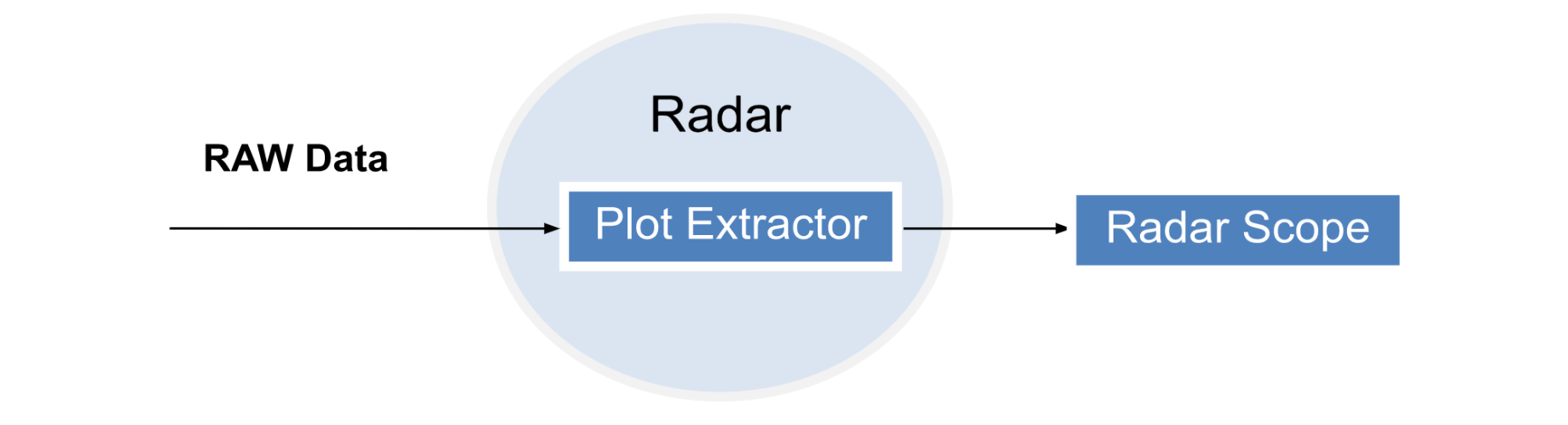
Coming back to where we left off, data is processed by passing through assembly, analysis, and formatting stages. This processing of data results in the generation of information. The surveillance data in RAW form is processed at the Radar end through a plot extractor.
The plot extractors work by distinguishing the surveillance data from other irrelevant input that is coming along. It segregates the data structure. The segregation is done by separating the required data of the target from ground clutter like terrains in that area, man made structures, weather clutter, and other objects like a flock of birds and intrinsic and extrinsic noise factors. As a result of this processing, a plot is generated and displayed on the radar scope.
Before going into further details let us understand what a plot is?
The radar receives the echoes coming from multiple targets at its antenna. This received echo contains information that is detected against the background noise. The detections provide information related to range and bearing and are termed plots. The plot is a term that is generic and associated with a tracking function input. Several pulses are being returned from a target toward a radar and help in improving detection quality. The process through which all of these radar pulses summed up is called Integration. As a result of digital integration of the received echoes, RAW surveillance data is generated.
This data report contains range and bearing information. Secondary Surveillance Radar generates a report that has additional data on identity code and level. These reports that have been generated are termed plots. These plots appear on the radar as blips if primary radar is in use. If secondary radar is in use then a cross appears on the screen. Although there is a level of processing involved we cannot consider this to be a refined processing. So far as an air ATSEP and air traffic controller we have RAW data. There is a plot where we have information related to its bearing, range, and identify code and level. But still, so far we cannot conclude details related to this target. All of the information is related to what is apparent as result of self-interaction and self-assessment of radar utilizing the signals being disseminated.

Good to Know
Range data of the plot is generated based on the two most common modulation techniques that are used in radar to measure the range from a target.
Frequency Continuous Modulated Waveform
In this technique, the frequency signal that has been sent and the signal that has been received in return is compared. The difference between the frequency difference helps in detecting the range of the target. The range to the target is proportional to this frequency difference, which is also referred to as the beat frequency.
Pulsed Doppler Technique
Radar working with this principle emits the signal for a short duration of time and waits for the return signal. The time difference between the signal that has been transmitted and the signal that has been received is used to calculate the distance from the target.
The tradeoff between FMCW and Pulse-Doppler radar
The minimum time difference required between transmitted and received pulse must be within a certain limit in the case of Pulse-Doppler radar. This minimum time difference of Pulse-Doppler radar in comparison to FMCW (Frequency-Modulated Continuous Wave) radar is larger, making it disadvantageous in the wider horizon of its applications. Whereas because of the short duration of pulse generation promises the power of the signal being transmitted is larger as compared to the signal transmitted in the case of FMCW radar.
Required to Know
Irrespective of the modulation technique all radars operate 360 degrees. In other words, their antenna revolves in all directions. The exception lies with the precision approach radar that is towards a specific direction. When the radar revolves and completes one circle from 0° to 360° this is called 1 Sweep. The radar collects data during this movement. The data that is being collected as already discussed is RAW Data which generates a plot.
Track Generation
Imagine a radar antenna completes its first sweep and RAW data is collected. Then in the second sweep, another set of RAW Data is acquired by the radar system. The third sweep generates another set of data. A minimum of three sweeps of data is required to generate a track.
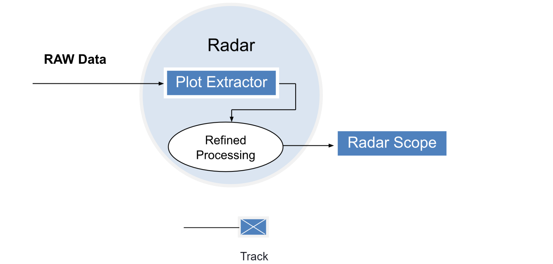
Refined Processing an Ultimate Requirement for Track Generation
Just acquiring the data is not enough; there is one important requirement: Remember the minimum requirement for data acquired during three sweeps. The rationale behind this is that it provides sufficient data for the system to generate a generalized overview of the situation related to the object. This refined processing of adequate data helps the system to generate predictions about the most probable position of the target in a specified time interval ahead. And the target generated is termed a track.
Mode S Coupling More Details With Track
Now-a-days,modern radars have been provided with Mode S. Mode S allows the ground-based equipment to communicate automatically with the airborne equipment that is ADS. This allows even further more refined processing of data that is being received from the ADS. With this data, an air traffic controller can have more critical details necessary for the provision of efficient air traffic control services.
Mode S sets the ground station in interaction with a target to acquire information available in the airborne equipment. After getting decoded, the data provides more detailed information. Previously controllers did not know what level an aircraft is aiming towards. The controllers had to rely on the belief that the pilot will be climbing or descending to the level being assigned. But now air traffic controllers can even have information related to the level that has been fed by the pilot in the system.
In nutshell now they can have details regarding the actual rate of climb and descent or level assigned etc. that is reflected in the aircraft system.
Required to Know
Envision an air traffic control environment where a controller is working in front of a radar screen. There is a lot of traffic. His attention to all of the targets is compulsory to ensure separation. Imagine suddenly some of these targets split into two.
We can imagine what sort of stress can be created on an air traffic controller and how critical this situation can be for the safety of air traffic.
But is this possible? Well yes, this situation can take place. In common ATC language, we term this situation as double targeting. Because this is what an air traffic controller is observing on the scope. The dilemma it creates is that it becomes difficult for the controller to assess which target is the real one.
Double Targeting
This is an error related to the plot or track. In this situation, the target splits into two instead of one solo target. And these targets are at two different positions.

What is the reason for double targeting?
Radar Coverage and Overlapping Region
We all know that it is not just one radar but several radars have to work together to provide coverage all across the country. These radars are working together to ensure continuous monitoring and surveillance services in all parts of a country. These radars have a specified coverage. Beyond the coverage of radar, another radar is working to provide coverage in that gray area so that aircraft will remain continuously under consistent monitoring and surveillance. All radars have a coverage pattern in a circular form. As several radars work to encapsulate all of the areas there exist overlapping regions. The aircraft in these regions receive signals from the radars covering this area. As the aircraft is in overlapping regions hence it will be receiving signals from multiple radars. These radars are receiving the reflected pulses at the antenna.
Formation of Double Target and Auto Rectification
These radars sometimes are unable to predict the fact to which radar this target belongs and both start generating targets at the radar scope. As a result of this confusion at the machine end the same target gets split into several targets. Radars try to figure out this error automatically based on algorithms. Radars have a specific threshold time that stands to be the bare minimum during which they are easily able to predict to which radar this target belongs. And as radars predict through the algorithm the double targeting is self-rectified. In a real-life scenario, such double targeting appears for a very short period. Generally speaking, as they appear there they go in a blink of an eye. This is the sophistication level of new radar technology.
Role of Ionosphere in Track Error
Double Targeting can also be an outcome related to the phenomenon of the ionosphere. The time factor can be undetermined under such a scenario.
We all know that the Ionosphere acts like a mirror for radio waves. It starts from 50 km above the earth's surface. It is an ionized region of the air. You probably would be thinking about how air is ionized. The solar radiation coming from the sun is responsible for the ionization of this layer hence named as Ionosphere. The electronic nuclei and their electrons are separated because of this ionization process. Hence in this region of airspace, we find oxygen ions and electrons instead of oxygen in gas form. Because of this fact, this layer is electrically conductive as it has moving charges, not just neutral molecules. GPS signals are significantly affected when they travel through this layer. And this impact is catered by the utilization of Wide Area Augmentation Systems and other Satellite Based Augmentation Systems (SBAS). As the signals from GPS travel through the ionosphere, these signals are refracted and are slightly delayed. This delay results in incorrect positioning of the plot or track. The ionosphere shows an uncertain environment.
Utilizing GNSS With GPS Integrity Monitoring
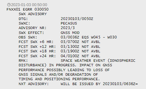
As the GPS signals are refracted and slightly delayed due to the ionosphere. Because of this fact GPS is not used directly for operations instead GNSS is used in which GPS integrity monitoring is mandatory. Moreover this happens normally during sun outage timings. Sun outages, or solar interference, happen when the sun, the satellite, and the receiving station at earth are all in alignment. Conjunction of the Sun and Satellite is the technical term for this circumstance.The disturbance in the ionosphere can impact GNSS performance, possibly leading to loss of GNSS signals and/or degradation of GNSS signals and/or degradation of timing and positioning performance. Normally when this air is turbulent an advisory is generated by the Met authority.
Imagine during the first sweep of radar GNSS data was received. But in the second sweep data received with delay due refraction. As a result of this intermittent flow of data due to disturbance in ionosphere position, related information becomes erroneous. The impact of solar radiation cannot be completely mitigated. even in the presence of SBAS. The augmentation system corrects this error by identifying the pattern in which the ionosphere is interacting with the signal and then it generates the correction data based on the current atmospheric conditions. But one should not forget that even Wide Area Augmentation Systems as well as Satellite Based Augmentation Systems can be impacted by major space weather events. And the time the probability related to it turns into reality then at the same time probability for the double target phenomenon increases. As ionospheric disturbance is uncertain so is the occurrence of double targeting.
The same situation can take place with a longer time duration when the transmitter of the aircraft is disseminating incorrect ADS data. This situation can create a problem of double targeting by resenting the target at two different positions.
Algorithm-based Multiple Sensor Tracking System
Prevention of double targeting requires the utilization of an effective algorithm-based Multiple Sensors Tracking system to identify from which target source the data is coming from. These algorithms help in identifying data that pertains to radar. If data is not related to radar it is neglected and when it is identified as radar data then the output is reflected on the scope. These algorithms can even rectify the erroneous message generated by the ADS. As a result of this atomization, the double targeting issue is resolved and a single target is depicted in the right location. So we can consider these algorithms as a technique of auto adjustment.
Solution
- ATSEP should monitor data related to the target in detail for clues.
- ATSEP should observe aircraft trajectory that will be depicted on the radar scope and data related to its trajectory.
- The aircraft message that has been received should be observed and compared with the trajectory to confirm if there is no error within the message.
- After it has been confirmed that an error exists within the aircraft message that has been received then ATSEP should wait as the problem will itself get resolved shortly by the algorithms.
- If there is a reasonable surety that the message is correct then ATSEP should try to correct the source that is having the issue instead of jumping somewhere else.
- There is a provision for the air traffic controller to have a selection of multiple radar combinations. A controller can select multiple radars at the same time and even can go in a mono view. Hence as an ATSEP, you can advise the air traffic controller to observe a change in double targeting while selecting different radars one after the other. In this way, if an error is related to radar then there exists a possibility that the deselecting that radar double targeting issue will be resolved. If the radar scope with the same provision is available with the ATSEP then they should follow the same themselves.
- This troubleshooting technique is a systematic process for problem solving. It involves gathering information on an undetermined complex issue and trying to find the thread head from a clustered thread step by step. This technique is based on best-known practices for a specified case scenario and hit-and-trial methods.
- Never forget to follow the following steps one after the other
- Aquire Information (What is happening?)
- Define the Problem (Double Targeting)
- Identify the most probable cause (Radar Source, Transmitter, Ionosphere phenomenon, Overlapping Regions, Other)
- Generate a plan of action (How to start and rectify this problem?)
- Implement plan (Message Correct then go for source and if message incorrect than wait or try to change radar selection)
- Analyze results (Observe changes in double targeting)
- Document the whole process that has been adopted.
SkyRadar's Radar Training Infrastructure
SkyRadar provides Training Radars and Simulators to generate raw data in training environments.
FreeScopes provides algorithms needed in Air Traffic Control. It produces plots and tracks and gives various intelligent algorithms for movement detection and tracking.
The solution is vital for modern ATCO and ATSEP qualification. It makes the step from the theoretic understanding of the radar image to typical conventions on how target plots and tracks are displayed. Beyond that, it allows students to apply solutions and fixes for erratic plots and tracks.
The integration of SkyRadar's pedagogical system monitoring and control solution allows to assemble bespoke training solutions for ATSEP, customized on each training academy and budget.

Annexe
|
Nr. |
Type |
Appearance |
Reason |
Rectification |
|
1 |
Double Targeting |
Two Targets of same aircraft appear on radar scope |
Overlapping Radar Echoes. Double Targeting can also be an outcome related to the phenomenon of the ionosphere. |
radars predict through the algorithm within their threshold time regarding actual source of signal as a result the double targeting is self-rectified utilization of an effective algorithm-based Multiple Sensors Tracking system ATSEP to
|
|
2 |
Merged Target |
Two separate targets are tracked simultaneously by a single radar system and appear as a single merged target |
Overlapping Radar Echoes. Failure of Radar Signal Processing algorithms to separate the return from two targets. |
Investigating the cause of the problem The ATSEP would analyze the radar data and system logs to identify the root cause of the issue with merged targets. Testing and verifying the radar system The ATSEP would perform tests on the radar system to verify its functionality and check for any errors or faults. Updating software or adjusting system settings If the issue is related to software or system settings, the ATSEP would update the relevant software or adjust the settings to resolve the issue. Checking the radar antenna If the issue is related to the radar antenna, the ATSEP would check it for proper alignment and any other issues that may cause merged targets. Adjusting the radar's processing algorithms If the issue is related to how the radar processes the data, the ATSEP would adjust the processing algorithms to resolve the issue. Monitoring the radar system After rectifying the issue, the ATSEP would monitor the radar system to ensure that it is operating correctly and that the issue with merged targets does not reoccur. Preventive Measure To mitigate this issue, radar systems may use advanced signal processing techniques or multiple radar beams to separate the returns from multiple targets. |
|
3 |
De-correlation |
Synthetic Track Move apart from actual target |
Correlation Issue. Incorrect Flight Plan information like estimates or Squawk Code. |
Correct the information in the current Flight Plan of the target Aircraft like its estimates and Squawk Code. |
|
4 |
Target Jump |
Target appear jumping from one position to another position |
It is observed in radars with high revolution per minute and small area of coverage like 5 by 5 NM. (Like SMR, Terminal Approach Radar). Another Factor is speed of aircraft that supplements. Normally it is observed when an aircraft is departing because it has more speed while takeoff. Note: SSR won’t show as the area of coverage is greater in Nautical Miles. Another Reason may be problems with the SMR system, such as interference, data processing errors, or technical faults in the equipment. |
Investigating the cause of the problem The ATSEP would analyze the SMR data and system logs to identify the root cause of the jumping target issue. Testing and verifying the SMR system The ATSEP would perform tests on the SMR system to verify its functionality and check for any errors or faults. Repairing or replacing faulty components If the ATSEP finds that a component of the SMR system is causing the jumping target issue, they would repair or replace it as needed. Updating software or adjusting system settings If the issue is related to software or system settings, the ATSEP would update the relevant software or adjust the settings to resolve the issue. Monitoring the SMR system After rectifying the issue, the ATSEP would monitor the SMR system to ensure that it is operating correctly and that the jumping target issue does not reoccur. |
|
5 |
Reflection |
Target appear as being farther away at great distance or closer than its actual position or a incorrect altitude of a target on the radar display |
It happens because of angle at which the radar signal is transmitted and received, the curvature of the Earth, and atmospheric conditions |
Investigating the cause of the problem The ATSEP would analyze the radar data and system logs to identify the root cause of the issue with the radar target reflection. Testing and verifying the radar system The ATSEP would perform tests on the radar system to verify its functionality and check for any errors or faults. Applying filters If the issue is related to false reflections or interference, the ATSEP would apply filters to the radar display to remove these unwanted signals. Adjusting antenna design If the issue is related to multipath reflections, the ATSEP would adjust the antenna design to reduce these reflections and improve the accuracy of the target information. Minimizing clutter If the issue is related to clutter in the radar display, the ATSEP would take steps to minimize the reflections from non-moving objects and improve the visibility of real targets. Updating software or adjusting system settings If the issue is related to software or system settings, the ATSEP would update the relevant software or adjust the settings to resolve the issue. Monitoring the radar system After rectifying the issue, the ATSEP would monitor the radar system to ensure that it is operating correctly and that the issue with the radar target reflection does not reoccur. Note: Radar uses multiple filters for this purpose. Hence wait for self-rectification by radar. |
|
6 |
Target Maneuver |
The radar may display the target as moving in an unexpected direction or at an unexpected speed. |
Caused by the rapid acceleration or deceleration of an aircraft, which makes it difficult for the radar system to accurately track the target's movement |
Use of multiple radar systems or frequency bands can also help to reduce the impact of target maneuver related issues. |
|
7 |
Target Angel |
It may appear as flock of targets on screen as blip etc |
This happens because of flock of birds or other objects |
Identifying the cause of the issue The ATSEP would first determine whether the target error is indeed due to weather phenomena, such as heavy rain, snow, or thunderstorms. Monitoring weather conditions The ATSEP would continuously monitor the weather conditions to determine if they are affecting the radar system. Evaluating the radar system The ATSEP would evaluate the radar system to determine if it is functioning correctly and check for any faults or errors. Adjusting the radar's processing algorithms If necessary, the ATSEP would adjust the radar's processing algorithms to compensate for the effects of weather phenomena on the radar signals. Communicating with air traffic control If the target error is affecting air traffic, the ATSEP would communicate with air traffic control to provide them with updated information and assist them in making any necessary adjustments. Monitoring the radar system After taking any necessary actions, the ATSEP would monitor the radar system to ensure that it continues to operate correctly and that the target error does not reoccur. |
References
- Frequency-Modulated Continuous-Wave Radar (retrieved 26.12.2022), by radartutorials
- Measuring and Modeling the impact of the ionosphere (2016), by bham
- Pulse-Doppler signal processing (2019), wikipedia
- Why FMCW is winning the race share (2018), pathpartnertech
- Plot Extractor (retrieved 26.12.2022), by radartutorials
- Mode S Surveillance Principle (2019), by ICAO
Troubleshooting (2022), by techtarget - Space Weather Advisory Service (2023), by ilmailusaa