


The Moving Target Indication algorithm provides the capability to detect reflections coming from targets in motion with respect to a standing background environment, such as ground, walls, parked cars, and so on.
A basic implementation of the MTI techniques consists of only two steps:
-
- Signal delay operation and
- Subtract operation
This normal technique of MTI does work well in environments where the moving targets do reflect way more power to the radars in comparison with the standing targets or clutter. However, in cases where the standing targets are strong reflectors like corner reflectors, which might shift the signals in phase although the target itself is standing; or large trees, leaves of which might tend to move or swing from wind but the tree itself is not moving; the basic MTI technique does not detect these situations correctly. This might lead to signal leakage concept, where we wrongly would detect a target as “moving”, although the target is a standing one.
Moving Target Indication Post Process
For solving the above described shortcomings in real case scenarios, we provide an enhanced implementation of the MTI, which we refer to as MTI PP – Moving Target Indication Post Process. It is also part of the FreeScopes ATC I set of blocks. The MTI PP does not use only the initial principle of the MTI technique, but it also employs two other steps to omit a possible signal leakage, which leads to a false positive detection, as it can be seen in Figure 1.
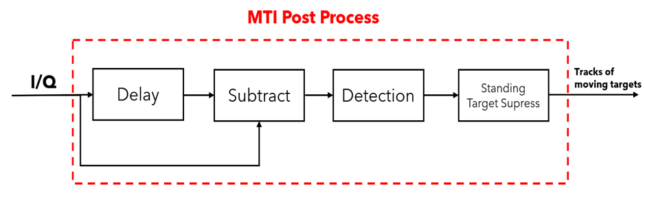
Figure 1 MTI PP
In the following, we describe the operation of each block from Figure 1.
Delay and Subtract block
The Delay and Subtract block, incorporate the basic MTI technique. In literature you will find this method also as the clutter canceller technique.
This approach subtracts the envelope of the current returned signal and the previous returned signal. The delay itself equals one interpulse period T=1/f_r. The output signal represents the change on the envelope. If a moving target is detected the variation on the output signal is emphasized, while for standing targets it is minimized.
After the MTI algorithm, a detection on the signal is performed. In this case we do a hard coded threshold, where the user might determine it as an input parameter. A simple pseudo code of the method is presented in the following:
if signal power>threshold:
signal power=signal power;
else:
signal power=0;
STS – Standing Target Suppression
After the detection has been made, we present another pre-processing step on the MTI PP, called STS – Standing Target Suppression. The STS method is a parametrized technique which distinguishes between moving or standing targets based on their returned power, coming from the normal MTI and detection method.
To remove possible signal leakage coming from any false positive detected target as moving from the previous steps, the STS algorithm uses the form of the power spectrum of the returned signal. If the received power is coming from a moving target, it will be spread over more distance cells for a specific angle position, in comparison with the standing target, which power might be represented as short and quick impulses, as it can be seen in Figure 2.
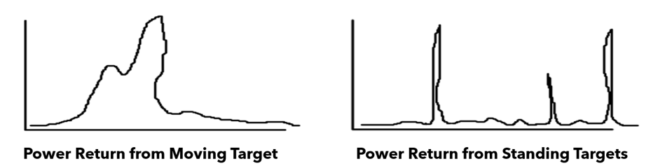
Figure 2 Power returns from moving and standing targets (manually sketched)
The STS method employs snippets or short windows to capture these power returns. If the signal will be spread within a complete window length, then the signal is most likely reflected from a doppler-target, otherwise it is reflected from a standing one.
Integrating All Blocks
After the last pre-process step of the STS, the MTI PP method is complete and delivers the signal tracks of a moving target which can be clearly seen on the PPI Scope, as stated in Figure 4. In Figure 3., you see the output of a normal MTI shown on the PPI scope. Interesting to be observed are the tracks of the signal between the angles 180° and 190°, because they are the so-called signal leakages, since these power returns are coming from a wall placed some meters in front of the radar. This is also the drawback of using only the MTI method for such scenarios.
Furthermore, in figure 4 you can see the same scenario, where we conducted the measurement once again with our MTI PP, and as expected between angles 180° and 190° there are no tracks to be seen, which previously were coming from a wall in front of radar. Thus, the MTI PP shows significant improvements in comparison with the normal MTI operation.
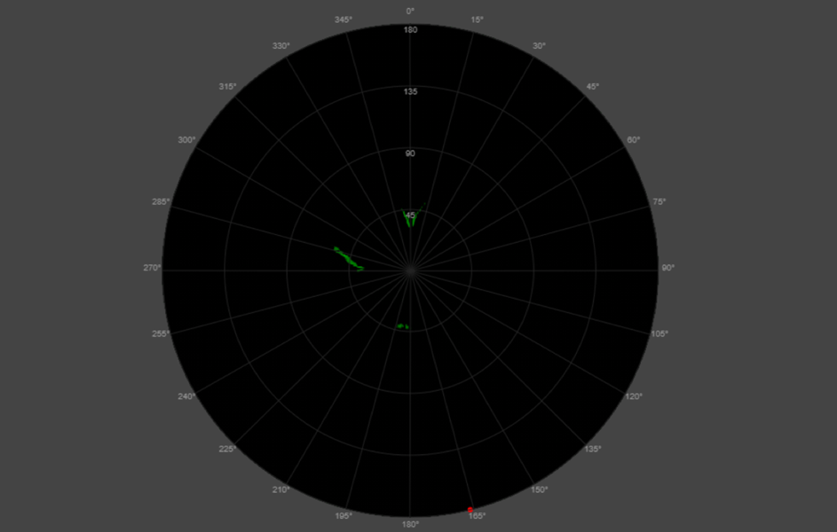
Figure 3 The output of a trivial MTI, shown on the PPI Scope
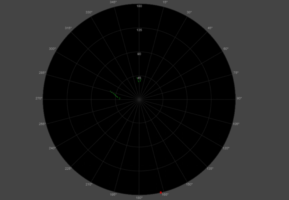
Figure 4 The output of MTI PP, shown on the PPI Scope
MTI PP in FreeScopes ATC I
The Moving Target Indication Process including post-processing is implemented in FreeScopes ATC I.
MTI has several technical limits. For example it misses moving targets when they stand still. Therefore many modern radars implement the Moving Target Detection process, which is also part of FreeScopes ATC I. Read more about MTD in the article: The Enhanced Moving Target Detection in Radar Technology.