


The Moving Target Detection is a highly reliable algorithm for detection of moving targets and temporarily non-moving targets in the constant presence of clutter. It is implemented in SkyRadar's ATC I Module.
Basic MTI with Post-Processing
The block diagram of the used simple MTD as deployed in SkyRadar's FreeScopes ATC I module is shown in Figure 5.
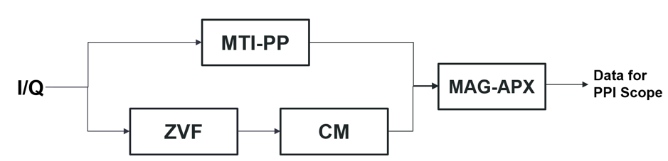
Figure 5 Moving Target Detector
In this configuration MTD consist of four sub-blocks:
-
- MTI – PP Moving Target Indication Post-Process
- ZVF – Zero Velocity Filter
- CM – Clutter Map
- MAG-APX Magnitude Approximator
In the FreeScopes ATC II module, advanced students and trainees can compose and vary their specifc MTD by assembling it from scratch with subcomponents (MTI-PP, Zero Velocity Filter, Clutter Map, Magnitude Approximator, ...) .
Zero Velocity Filter
As the upper path of this block diagram was already discussed on the MTI article, the next block to be introduced here would be the ZVF.
The zero-velocity filter represents a filter which filters out all the doppler-targets and passes only the standing targets, doppler of which equals to zero. This filter on the lower path of MTD block diagram serves also as the real time estimator of the mean clutter power because this information will then update on real time the stored clutter map. The principle of the ZVF here is the inverse MTI.
.png)
Figure 6 The difference between the MTI and inverse MTI (ZVF)
Since MTI does detect the moving targets, an inverse MTI would detect the zero-Doppler targets, in our case called the ZVF. In Figure 6., you can see the difference between these two filters and how the ZVF does estimate relevant clutter information used later as input for CM.
Clutter Map
The CM – Clutter Map is an innovation employed in MTD, for controlling the false alarm rates against spatially nonstationary clutters.
The clutter map can be understood also as a big matrix which stores the reflected clutter power for a whole radar sweep (360°) from the stationary background. After one whole radar sweep, the operation of MTD begins, and in this way also the clutter map is synchronized with the angle position of the radar, and in this way, it will be updated on real time basis from the output signal coming from ZVF.
The output signal of ZVF is coherently integrated with the with the stored signal in clutter map for the respective compass position (angular position). The updated information on the clutter map then will be forwarded to the MAG-APX for comparison with the signal coming from the MTI PP.
Magnitude Approximator
With the next block, the MAG-APX Magnitude Approximator is introduced, like the MIT Lincoln Lab, who developed the MTD for air traffic control, also we in Sky Radar team use this algorithm for comparing, detecting, and estimating clearer Doppler-target tracks on the PPI scope.
The main aim of the MAG-APX is to compare the peaks or main power targets from MTI PP and CM, and from here decide if the radar did detect a Doppler- or a stationary-object. As it can be seen in Figure 7., the output signals of the MTD algorithm represent clear tracks of moving objects on PPI scope.
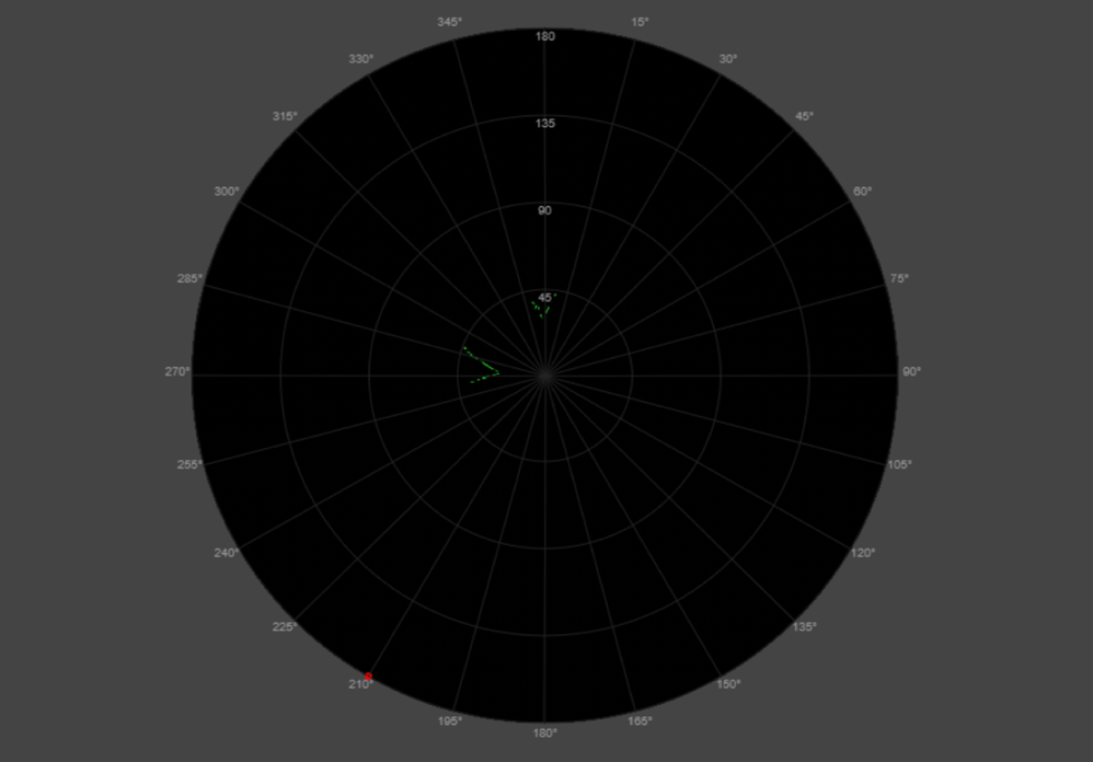
Figure 7 The output of the MTD shown in PPI scope
MTD with Doppler Filter
In the following chapter we introduce an advanced/extended version of the MTD algorithm. The MTD-DF Moving Target Detector Doppler Filter incorporates an additional filter or detector as it can be seen in Figure 8.
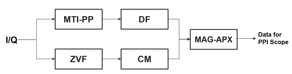
Figure 8 Moving Target Detector Doppler Filter
The difference between the MTD and MTD-DF is the additional Doppler Filter method.
The DF technique is developed as a phase detector in order to make the upper path more robust form possible complex background clutter environments. The main aim of this block is to detect the phase shifts from two consecutive pulses. These phase shifts are then compared with each other and in this case the filter serves as a plausibility method of the output signals from the MTI-PP. Two consecutive pulses which have a Doppler-frequency will not have a regular/expected phase shift in comparison with two consecutive pulses of stationary targets.
The idea of these phase shifting concept is shown in the following sketch, in Figure 9.
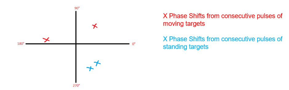
Figure 9 Phase shift detector
The additional Doppler filter algorithm makes the MTD-DF even more reliable and highly accurate for detecting Doppler-targets, in comparison with the pure MTD method. However, the simple MTD can also be deployed in more basic radar sources which do not have a Doppler feature included.
Read more articles about the features included in the FreeScopes ATC I module.